Measure twice, cut once

This is an example of why you always check your assembly tolerances as you’re putting an engine together.  The image that follows is the cam sprocket from an Edelbrock 7814 set I purchased last week.

Defective cam gear
Defective Edelbrock 7814 cam sprocket

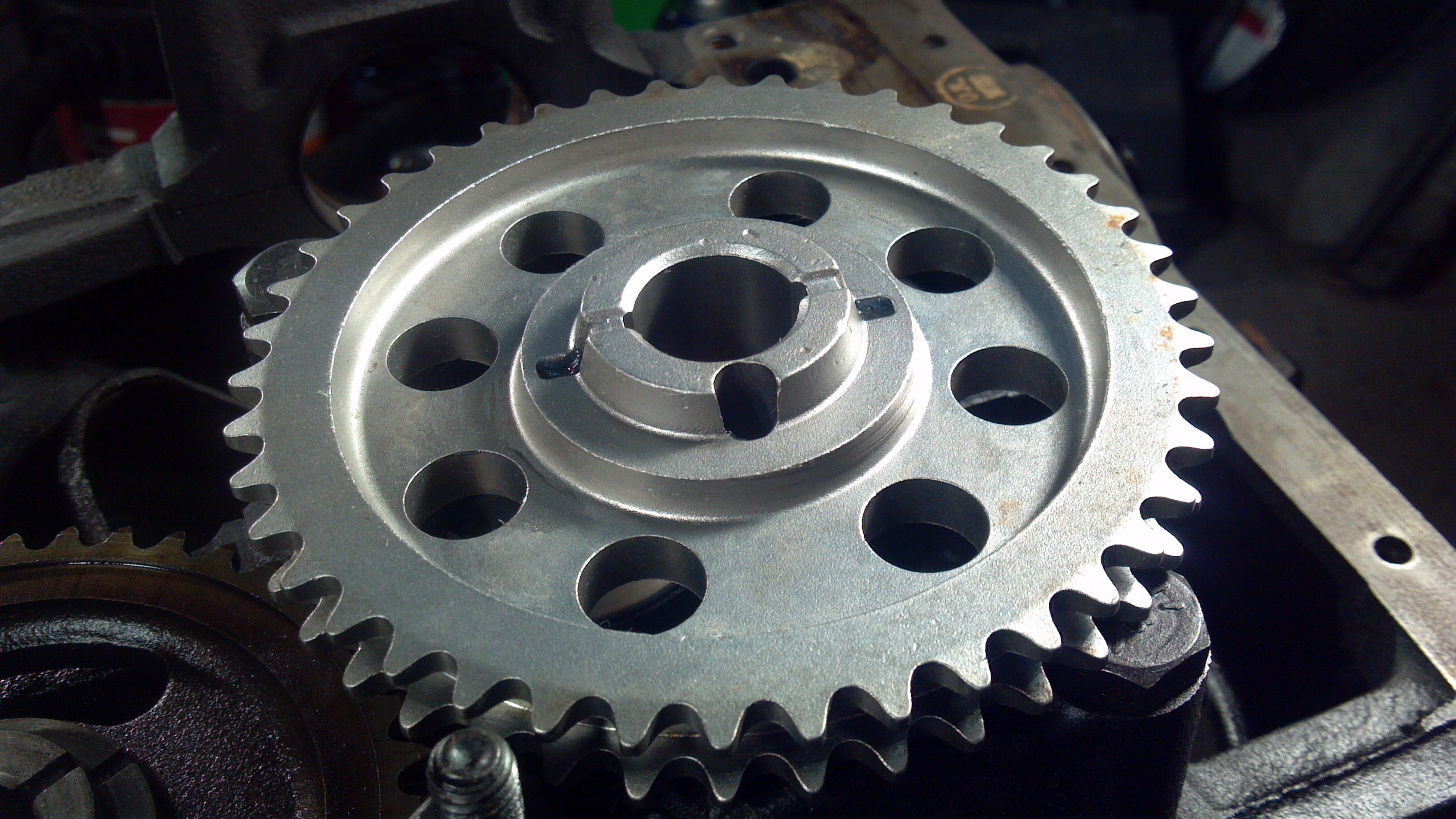
Can you spot what’s wrong already?  If you can’t see it in the view above, click the link to the full resolution of the photo.

Ford uses a simple system to control camshaft end play.  The sprocket face above bolts to the end of the front cam bearing journal, creating a gap between the second step on that sprocket and the journal face.  Sandwiched in that gap is a hardened steel or cast iron camshaft retainer plate.  The difference in thickness between the gap and the plate thickness ends up being the end play.

When putting together an engine, my normal procedure is to install the cam, bolt up the cam sprocket temporarily so that I can check end play while it’s easy to get to, and then remove the cam sprocket and proceed to the crank and the rest of the rotating assembly.

Since I always measure and remove anyway, I didn’t pay too much attention to the new cam sprocket when I was installing it last night, which gave me ZERO end play once installed.  The cam would turn by hand, but I was probably less than a thousandth of an inch of luck from full bind.  Of course, running the engine in this state probably would have lunched the build very quickly, which is why it’s best to measure everything as it goes together.

I was re-using the original cam with a new camshaft retainer plate, so my first thought was a machining error in the Ford plate.  I swapped to the old Ford retainer plate and got the exact same result.

I’d have saved myself about ten minutes of head scratching if I’d looked at the sprocket first.  If you look at the two protruding faces, neither is machined.  They are both as-cast surfaces.  You can see a bit of the hub of the original sprocket in the bottom left of the photo, for a comparison of what that finish should look like.  Or, just take a quick peek below.

Simply put, someone at the factory making this part for Edelbrock just missed a step.  At some point during manufacture of this piece, it should be chucked in a lathe, and those two surfaces turned to meet the end play tolerance.  Someone just missed it.  This surprised me, since it’s the only defective part I’ve ever personally gotten from Edelbrock.

Luckily, a phone call quick trip to Advance the this morning before work got me a part that was completed.  I’d bought their only 7814 in the region, so I paid another $12 and swapped to an Edelbrock 7811, which is interchangeable with the 7814 other than a pair of extra keyways to advance and retard the cam timing.  Problem solved, no hassle, and my one Edelbrock “oops” will go back to them.

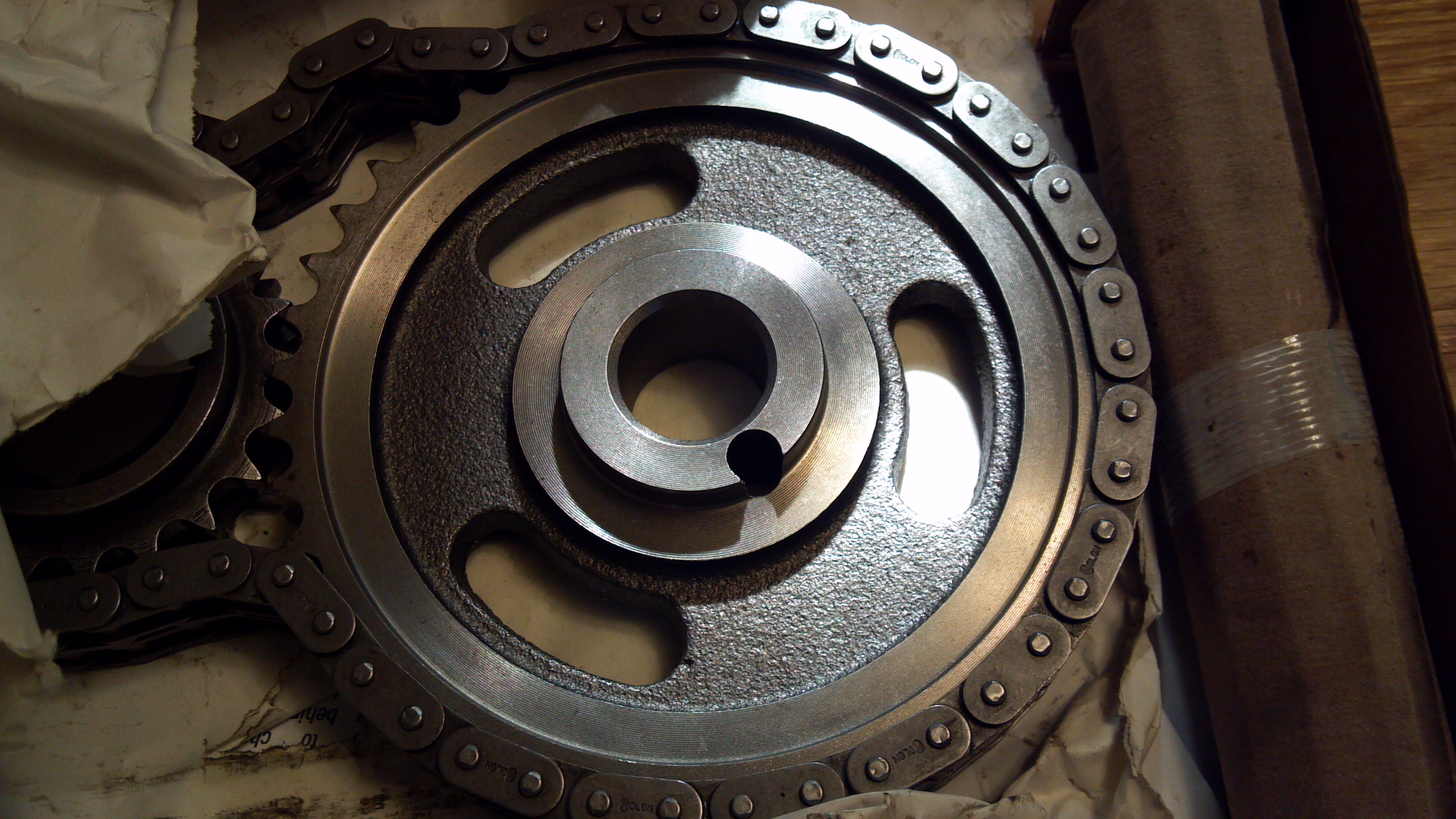
Here’s the 7811 with the correct machining.  You can see there are four lathed surfaces here that were missed on the first one.

Edelbrock 7811 sprocket
Edelbrock 7811 cam sprocket

A Note on Measuring Camshaft End Play

I’ve noticed a very common and very critical omission in most of my shop manuals that turns up on forums fairly often.  Off the top of my head, this tidbit is missing in two Ford factory shop manuals I own (1993 Mustang and 1991 Truck), as well as a smattering of Haynes and other manuals I have.

All of these references instruct you to install the cam, install the retainer plate, check the camshaft end play (the tolerance is 0.0055-0.009 for fuel injected 302’s), and then install the timing set.

If you follow these instructions as they appear in every manual out there, you will do a lot of head scratching, because you’ll see anywhere from 1/10 to 1/4 of an inch of camshaft end play.  Don’t worry!

How to measure camshaft end play (the one and only way that actually works):

  • Install camshaft
  • Install retainer plate
  • Install and torque cam sprocket
  • Measure end play
  • Remove sprocket so that you can install remainder of timing set

Without the sprocket installed, the only thing controlling your end play is the plug in the camshaft bore all the way in the back of the block.  The sprocket must be installed in order to measure, but I have yet to find a manual that points that fact out, at least in my collection.

This little anecdote is personal experience, as I was one of the head scratchers the first time I ran into this.

Fuel octane myths

Higher octane fuel will give me more power!

This is the big one.  Unfortunately, higher octane fuels do not generally give you more power.  If only it were so easy.  A higher octane fuel has almost exactly the same energy as a lower octane fuel, and if all goes well, it burns identically.

There are exceptions to this in the automotive world — quite a few modern cars run knock sensors, and with a lower octane fuel, the computer will be forced to retard timing to prevent knock, which will typically cause power to fall off.  HOWEVER, this does not mean that a higher octane fuel will bring more power, only that running the grade of fuel the engine was designed for will provide optimum power on a car equipped with a knock sensor.  Once you reach a point where octane is sufficient such that the computer doesn’t have to pull timing, there are no more gains to be had.

Higher octane fuels burn hotter.

One common myth concerns the ignition/burn temperature of higher octane fuels.  Many people, including quite a few who should know better by now, continue to perpetuate the myth that higher octane fuels require more energy to ignite, or burn at a different temperature or rate (usually “more slowly”).  This is simply not true.  Though burn rate can vary between fuels with all other things being equal, this is not linked to the fuel’s octane rating, and other variables like mixture quality and distribution have a MUCH greater effect on burn rate.
Octane is also not directly a measure of the amount of compression it takes to initiate burn (preignition or detonation).  Although they are often connected, knock is not necessarily directly linked to preignition and detonation.  Knock, specifically, is a violent resonance of the gases in the combustion chamber, causing severe spikes in pressure and temperature, and usually audible from outside the engine.

It is possible for detonation (spontaneous ignition and simulaneous burn of the entire air-fuel mix ahead of the flame front created by the spark plug) or preignition (spontaneous ignition of pockets of flame ahead of the main flame front, caused by heat and pressure, which then burns at a normal rate) to occur without knock, and it is also possible for knock to occur without preignition or detonation.

This phenomenon was studied extensively in the 40’s via high speed camera by NACA (predecessor to NASA) when they were developing many of the more sophisticated late WWII era piston aircraft engines.  However, with the massive shift in research from piston to turbine engines at the end of the war, a lot of the NACA research was filed away and forgotten.  Their information, which is now freely available from NASA over the web, is a treasure trove of information on detonation, supercharging (including turbocharging, which is simply a form of supercharging), fuels, water injection, and even things as odd as using nozzles on jetted exhaust pipes to gain thrust (don’t get too excited, it doesn’t benefit much below about 250mph, and is useful mostly because propellers start to lose efficiency at higher speeds).

For more information, the NACA article covering knock and detonation can be found on the NASA Technical Reports server.  Search for NACA-TR-912 and enjoy!

Simple electric fan control

Want to make an electric fan control harness without having to buy someone’s expensive solid state setup?  See below for three ways you can go about it, depending on how many features you want.

  • All of these setups are based on a Ford Taurus fan, or something with a fairly equivalent amp draw (approx. 38A continuous once it’s running).
  • Relay SS74 marked in the diagrams is also equivalent to a NAPA ST85 or GP Sorensen SF74.  You need a continuous-duty rated relay, with a capacity of at least 60A and referably closer to 80A for reliability.  You also need the relay to have an isolated ground to work with these schematics.  You can do this with a BWD SS664, which is easier to find, but the diagrams would need to be modified to suit the different relay design.
  • FS8 is a temperature switch.  Very important, you need a switch that is normally open, not a temperature sender.  Here is where you’ll need to do some hunting, because you need to find something with the right thread for you to mount somewhere you can use, and with the temperature range you want.  FS8 used to be an easy pick for Fords with an adjustable temperature, but I haven’t been able to find it lately.
  • Other relays shown here can all be a standard Bosch style auto relay.  I’ve been getting mine from All Electronics for years.  No financial interest in them, I just find them to be a good supplier, and they seem to have the best price on these.

Scheme 1

As basic as it gets, here.  This one will run any time the coolant is over the set temperature, including with the car turned off.

Scheme 1
Electric Fan Control – Scheme 1

Scheme 2

This adds an AC Demand input to Scheme 1.  This wire is usually easiest to find at the system pressure switch in your underhood A/C system.  This wire will be powered all the time when your A/C is turned on from inside.  For most cars, there are two wires here – make sure you tap into the wire that heads for the interior, not the one that runs from the pressure switch to the A/C compressor clutch.  The compressor clutch wire will cycle on and off with A/C system pressure, the wire to the interior will not.

Scheme 2
Electric Fan Control – Scheme 2

 Scheme 3

This is the most versatile setup.  Here, we add a switch (run to the interior) which will allow you to turn the fan on manually, off completely, or allow the same automatic operation as the first two schemes.

Scheme 3
Electric Fan Control – Scheme 3

You can easily build off these schemes for more complex setups.  A relay added off the I terminal of the SS74 will provide the ability to turn off the fan automatically when the ignition is off, for instance.  One more relay, another sender, and a second SS74 will use both available speeds of the fan, though I’ve never personally seen much use for the low fan speed.

Please feel free to disseminate, modify, and enjoy!


Chassis Dyno technology

I’ve gotten into a surprising number of discussions over the years about dynamometer technology and sources of error.

Most research facilities and race teams using engine dynamometers have the expensive, high-tech kind.  They are basically an energy absorber, which can dissipate the engine’s energy real-time by turning it into heat, using electricity, hydraulics, or a number of other systems.  You crank up the engine power, set the dynamometer to hold the engine at a fixed engine speed, and measure the engine torque at either the engine mounts or the mounts for the energy absorber.  Math does the rest.  These systems are obviously relatively expensive, but they can measure engine output real-time at a steady state for hours, days, weeks, or sometimes months.

Because these systems are expensive, and obviously require you to have your engine out of the car, most enthusiasts do most of their measurement using chassis dynos.  Many chassis dynos are inertial dynos.  The drum you’re riding on is a tuned mass flywheel.  You measure torque and horsepower by using an accurate speed pickup on the drum to measure instantaneous speed and acceleration.  Rotational intertia of the drum times acceleration gives you torque applied to the drum (force).  Torque applied to the drum times the rotational speed of the drum gives you power.  The natural units for this system to work in are power and accelerative force vs. vehicle speed, because these are the things measured directly by the dyno — you don’t need any additional equipment or knowledge (of gearing, for instance) to figure this out.  This is also why a lot of not-well-set-up dynos like you might find at votech schools, etc. are only set up to give you power vs. road speed.

Now, how do you get this in terms of engine RPM?  You can either measure RPM directly or with an inductive tachometer, or you can calculate your RPM based on gearing and road speed.

This is all necessary to understand why you get different power outputs measured in different gears, which is a frequent source of questions I’ve encountered over the years.  You’re measuring power by measuring the acceleration of a system with a known rotational inertia (the dyno flywheel).  Now, your engine is linked to the drum via the transmission and driveline, so some of the power being produced goes into accelerating the crankshaft, clutch assembly, tranny innards, and wheels.  These automatically get factored out of the equation because you’re using the inertia of the flywheel alone to figure power — that’s why you’re getting wheel horsepower numbers, since it’s power after you subtract what is required to accelerate the driveline and wheels.  Basically, your first major error occurs because inertial dynos can’t measure at a static speed.

In lower gears, your engine/flywheel/input shaft are obviously turning faster in relation to the dyno flywheel.  Hence, you have to accelerate the drivetrain more in order to achieve the same dyno flywheel acceleration.  That takes power.  In lower gears, more power is taken up in accelerating the engine, leaving less to accelerate the car.  That’s why lightweight flywheels make a difference in low-gear acceleration, but practically none in high gear.  This shows up on the inertial chassis dyno as well.

Why might your dyno show less of a power loss in low gears, compared to someone else’s dyno?  Well, it depends on the flywheel mass of the dyno in relation to your power level.  You need a heavier flywheel to measure a more powerful car accurately, because you have more time during the runup to take accurate readings.  If you run on a heavy flywheel, the inertial mass of your driveline is small by comparison.  For the same power output, the entire system will accelerate more slowly, so you lose proportionally less power to accelerating the drivetrain.

This is certainly not the only way to measure power.  It’s cheap and simple, but it’s definitely not ideal, because as I mentioned the mass of the drivetrain/powertrain creates an inaccuracy.  To measure the true wheel horsepower (after friction losses, but before inertial losses), you need a dynamometer with an energy absorber – similar to the engine dynamometer we first discussed, but built into a chassis dyno.  These chassis dynos are based on driving the drum with a fixed, applied resistance from an absorber that can hold the drum speed steady.  These absorber systems can be water brake dynos, electric dynos, or even old school friction brake dynamometers, just like the options for engine dynos.  You measure the force needed to counteract the car’s output and maintain a constant measured speed.  It eliminates inertia from the picture, since the dyno will allow you to maintain a constant speed indefinitely (well, in theory, but the equipment has to dump all that waste energy somewhere ).  These are the dynos you use for serious development like tuning intake and exhaust systems, where you need the engine installed in the car but also need to maintain a given speed while measuring.

On the other hand, inertia dynos have a real advantage in telling you what your actual on-road behavior would be — assuming you have a drum the right inertia for the car.  If you tune it so that the engine on the dyno accelerates in gear at the same speed it would in that gear on the road (restrained by the mass of the car), then you will get a fairly accurate measurement of how much power you’re losing in that gear to rotational inertia.

Ford Duraspark wiring diagram

Duraspark wiring
Ford Duraspark Ignition wiring diagram

Here’s another useful tidbit out of my archives, source unknown.  Have a 60’s daily driver or cruiser, and want to eliminate points maintenance for very little cost, with easy to find, reliable parts?  Install a Duraspark II system.

I won’t repeat the many good guides on installing the system.  There’s plenty of information already handy on the web.  This early wiring diagram is handy, though, and one of the clearest I’ve seen.

5.0 Cam Specs

Ford 5.0L cam specs
Ford 5.0L (302) Cam Specs, 1985-1995

This scan has been floating around the internet for a while, and I honestly can’t remember where I found it.  It’s a scan from a Ford publication showing the selection of cams used in the 302 from 1985 to 1995.   Unfortunately it’s incomplete.  However, I’ve found that accurate factory cam data and specifications are actually pretty hard to come by, so I tend to collect this info when I can get it.

Enjoy!  Oh, and if you find more, or recognize the original source document – please let me know!

GearCalc spreadsheet

GearCalc Screenshot
GearCalc by Chuck Sanders

Over the years, I’ve developed my own spreadsheet for doing axle and speedometer gearing calculations.  It started in Excel, and now lives in Google Drive:

GearCalc on Google Drive

Please feel free to copy or download this calculator – like the rest of the site, it is shared under a Creative Commons license.

Features:

  • Supports up to six speeds, plus two ranges
  • Calculates speedometer drive gear for Fords, including speedometer error.  (This will work for some other makes as well.)
  • Shows the RPM after shift for each gear shift

How to Get Your Copy:

  • If you’re already a Google Drive user, click the “File” menu, and “Make A Copy.”  This will give you your own copy, which you can edit at will.
  • If you’re not a Drive user, you can click “File” > “Download As” to get a copy in the spreadsheet program of your choice.  You might have to do a little cleanup work to make it pretty again, but everything should work.

Instructions for use:

  • Fill in the (yellow) blanks with your information.  Vehicle and Trans fields are only there so you can keep track of your results if you choose to print this out.
  • Axle field should be obvious.  If you’re using a portal axle (Unimog, H1, aftermarket, etc) you’ll need to put your total axle gearing here, not just your differential gears.
  • Range can be 0 for single range cars, or the ratio in your transfer case for four wheel drives or trucks with splitters.
  • Tire diameter is in inches.  Your equivalent tire revs per mile will show on the right for the tire diameter you enter.  If you are going primarily by a manufacturer’s rev/mi figures, I’d recommend guessing your diameter until you get Rev/Mi correct as the fastest method.
  • Enter your transmission’s gear ratios in rows 11-16.  Unused gears can be left at “0”.
  • If you need revs at a specific road speed, you can easily change the speeds in row 10.  Engine revs below will change to suit the speeds you’ve entered.
  • Entering your shift point in row 38 will show you your road speed for each shift, RPM before and after, and % drop in RPM.

I’ve found this spreadsheet very useful over the years, and hope you do, too!  Please, feel free to leave any questions in the comments below.

What is A Turn Of The Nut?

Over the years, I’ve spent a lot of time on various online forums helping friends, acquaintances, and strangers sort out automotive problems.  I tend to lean toward the more technical end of car modification and design, and over the years, I’ve found out that there really aren’t all that many good automotive resources online.

What about the mountain of automotive websites out there?  Well, most of them don’t provide the sort of hardcore tech info I’m personally interested in.  Also, I’ve seen a lot of information on very authoritative looking sites that’s just plain incorrect, too.  I’ve looked at cars for years from the perspective of a designer who has to put numbers and tested data to everything, so maybe I just catch things that are below the level most people really worry about.

Either way, I’ve accumulated a fair amount of really detailed technical information (and some really useful tools, as well) over the years, and my goal is to gather the information I have and share it here for others to use.  Really, I’m here trying to create the blog I wish I’d found five or ten years ago.

You might find the occasional stray post here about buildings and engineering, but let’s be honest – we’re all here for the cars!

Here’s hoping you find it as useful as I might have then.

Chuck