I’ve gotten into a surprising number of discussions over the years about dynamometer technology and sources of error.
Most research facilities and race teams using engine dynamometers have the expensive, high-tech kind. They are basically an energy absorber, which can dissipate the engine’s energy real-time by turning it into heat, using electricity, hydraulics, or a number of other systems. You crank up the engine power, set the dynamometer to hold the engine at a fixed engine speed, and measure the engine torque at either the engine mounts or the mounts for the energy absorber. Math does the rest. These systems are obviously relatively expensive, but they can measure engine output real-time at a steady state for hours, days, weeks, or sometimes months.
Because these systems are expensive, and obviously require you to have your engine out of the car, most enthusiasts do most of their measurement using chassis dynos. Many chassis dynos are inertial dynos. The drum you’re riding on is a tuned mass flywheel. You measure torque and horsepower by using an accurate speed pickup on the drum to measure instantaneous speed and acceleration. Rotational intertia of the drum times acceleration gives you torque applied to the drum (force). Torque applied to the drum times the rotational speed of the drum gives you power. The natural units for this system to work in are power and accelerative force vs. vehicle speed, because these are the things measured directly by the dyno — you don’t need any additional equipment or knowledge (of gearing, for instance) to figure this out. This is also why a lot of not-well-set-up dynos like you might find at votech schools, etc. are only set up to give you power vs. road speed.
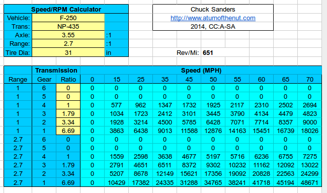
Now, how do you get this in terms of engine RPM? You can either measure RPM directly or with an inductive tachometer, or you can calculate your RPM based on gearing and road speed.
This is all necessary to understand why you get different power outputs measured in different gears, which is a frequent source of questions I’ve encountered over the years. You’re measuring power by measuring the acceleration of a system with a known rotational inertia (the dyno flywheel). Now, your engine is linked to the drum via the transmission and driveline, so some of the power being produced goes into accelerating the crankshaft, clutch assembly, tranny innards, and wheels. These automatically get factored out of the equation because you’re using the inertia of the flywheel alone to figure power — that’s why you’re getting wheel horsepower numbers, since it’s power after you subtract what is required to accelerate the driveline and wheels. Basically, your first major error occurs because inertial dynos can’t measure at a static speed.
In lower gears, your engine/flywheel/input shaft are obviously turning faster in relation to the dyno flywheel. Hence, you have to accelerate the drivetrain more in order to achieve the same dyno flywheel acceleration. That takes power. In lower gears, more power is taken up in accelerating the engine, leaving less to accelerate the car. That’s why lightweight flywheels make a difference in low-gear acceleration, but practically none in high gear. This shows up on the inertial chassis dyno as well.
Why might your dyno show less of a power loss in low gears, compared to someone else’s dyno? Well, it depends on the flywheel mass of the dyno in relation to your power level. You need a heavier flywheel to measure a more powerful car accurately, because you have more time during the runup to take accurate readings. If you run on a heavy flywheel, the inertial mass of your driveline is small by comparison. For the same power output, the entire system will accelerate more slowly, so you lose proportionally less power to accelerating the drivetrain.
This is certainly not the only way to measure power. It’s cheap and simple, but it’s definitely not ideal, because as I mentioned the mass of the drivetrain/powertrain creates an inaccuracy. To measure the true wheel horsepower (after friction losses, but before inertial losses), you need a dynamometer with an energy absorber – similar to the engine dynamometer we first discussed, but built into a chassis dyno. These chassis dynos are based on driving the drum with a fixed, applied resistance from an absorber that can hold the drum speed steady. These absorber systems can be water brake dynos, electric dynos, or even old school friction brake dynamometers, just like the options for engine dynos. You measure the force needed to counteract the car’s output and maintain a constant measured speed. It eliminates inertia from the picture, since the dyno will allow you to maintain a constant speed indefinitely (well, in theory, but the equipment has to dump all that waste energy somewhere ). These are the dynos you use for serious development like tuning intake and exhaust systems, where you need the engine installed in the car but also need to maintain a given speed while measuring.
On the other hand, inertia dynos have a real advantage in telling you what your actual on-road behavior would be — assuming you have a drum the right inertia for the car. If you tune it so that the engine on the dyno accelerates in gear at the same speed it would in that gear on the road (restrained by the mass of the car), then you will get a fairly accurate measurement of how much power you’re losing in that gear to rotational inertia.