And now, for something completely different.
This is an issue I ran into at work over the past week. We needed to get topography from a project I was working in BIM into ArcGIS for our GIS modeling folks. Days worth of googling revealed absolutely nothing useful – it was evident that someone had kludged together a few successful techniques back in 2009 and 2010, but there was absolutely nothing recent. Either BIM-based engineers no longer needed to get their info out to big-world GIS folks (unlikely), or no one who’s solved this problem since 2010 has taken the time to document it where the rest of the world can find it. It turns out the entire process takes about 15 minutes, but sorting out the process can take a week of frustration based on the information that’s readily available.
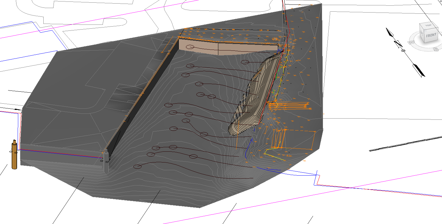
The problem: A Revit 2014 model, consisting mostly of site topography with a few “building”-like features. The model is built on a 2D survey with a vertical datum of NOAA NOS MLLW, and a horizontal datum of Virginia State Grid (South Zone) NAD 83. None of that really means anything electronically to anyone who isn’t trying to get a conversation going between BIM and GIS. The relevant part of the model in Revit looks like this, in 2D and 3D:
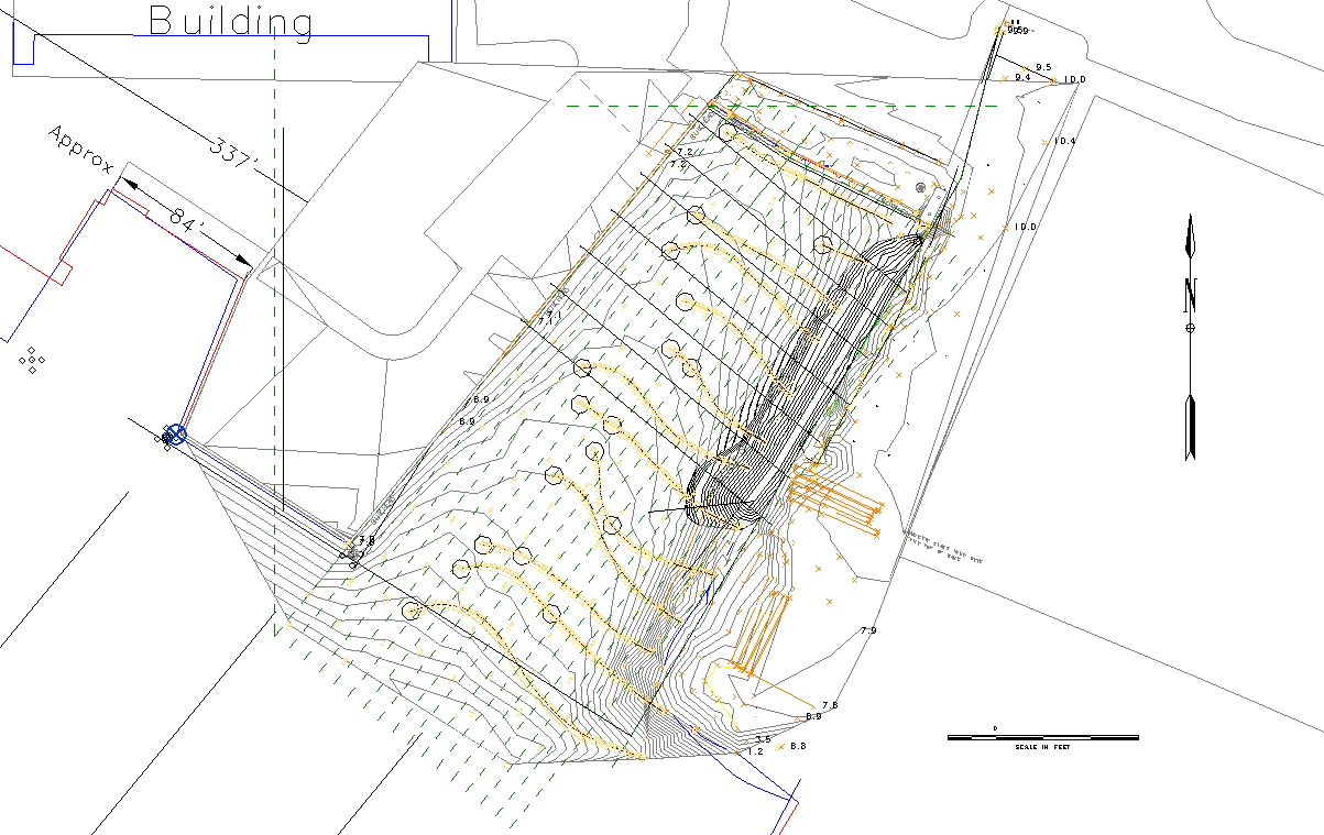
It’s important to note before we begin that you may need to export in both 2D and 3D to get your GIS coworkers everything they need. The 3D export will carry your model elements over, but they will often need contour lines for your topography, and contour lines are a 2D only element. The only way we’ve found to get both your elements and contours into GIS is by exporting a 2D contour set to go with the 3D model.
Revit has a lot of user confusion due to multiple coordinate systems. There’s an “internal” system that the user never sees, a “Project Coordinate” system controlled by the Project Base Point, and a “Shared Coordinate” system controlled by a Survey Point. Revit has limitations on how far parts of the model can lie from the internal origin, so it’s best to keep your Project Base Point somewhere near most of your actual model. In our case, the Project Base Point (and internal origin point) is a circular symbol to the left of the 2D, near the corner of a large flat spot that’s actually a helipad. We can’t move the Project Base point to our survey grid origin, since that’s 12 million feet to the west and far out of Revit’s comfort zone.
What we can do is put the Survey Point out there, thus setting the Shared Coordinates to match NAD83. This seems to work just fine. My file has a 1000′ grid of coordinates which are just out of view in the 2D above. To set the survey point, find the nearest convenient known point, and use the following tool: Manage tab > Project Location > Coordinates > Specify Coordinates At Point. You’ll need to use this tool once each for Northing and Easting.
What if you’re already using Shared Coordinates to coordinate between several discipline files? In that case, create an alternate Location. Go to Manage tab > Project Location > Location > Site:
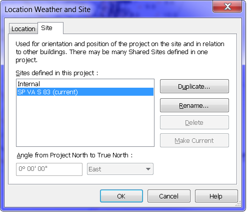
Click Duplicate… to make a new site, give it the name of your datum, and make it current. Now, you can go back to moving the survey point, and you’ll only affect the survey point for this saved Site. Once you’re done exporting, go back to this dialog, make your previous coordinate set current, and you’re back as you were.
Next, let’s export the 2D first. 2D exports are per view, so you’ll need to create a view at 12″:1′ scale containing exactly what your GIS team needs to see. Use VG to turn off everything extraneous, and set your crop region to exclude the large area of survey you might have in the file outside your project area.
Now, we need to set a few options. Head to R > Export > Options > Export Setups DWG/DXF (in my case at least – my GIS coworker knew she could work with DWG data to get the results she needed) to set up your 2D export options.
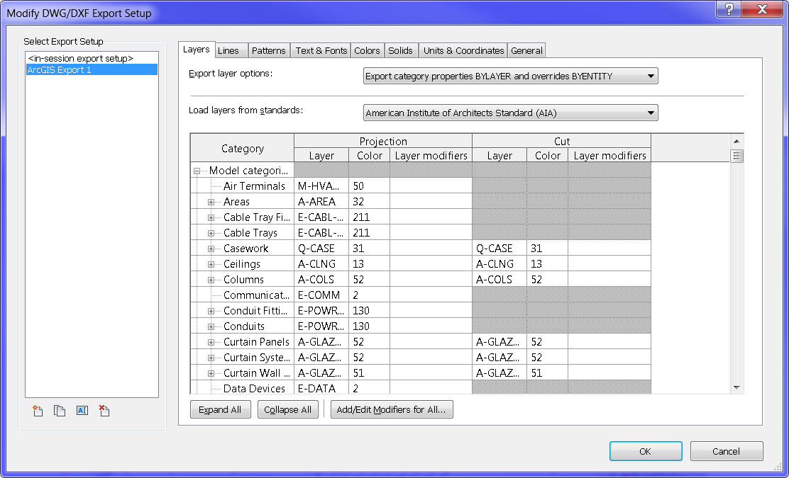
You could obviously spend half a day in here tweaking colors, layer names, and lineweights, but your GIS folks can override all that when they import anyway. The only important things to change are all buried in the depths of this dialog. First, hit the Units & Coordinates tab:
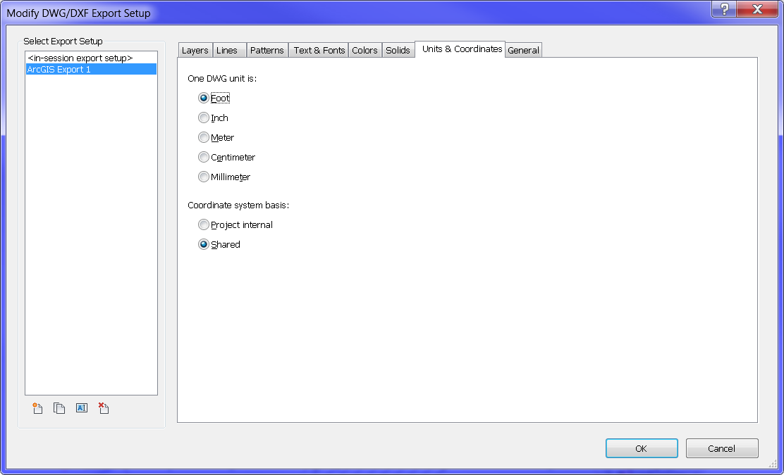
Change the DWG unit to Foot, and the Coordinate system basis to Shared, as shown. Our first attempts at this had the 2D importing at 1/12 scale, hundreds of miles away – these settings fixed that. Next, go to the General tab:
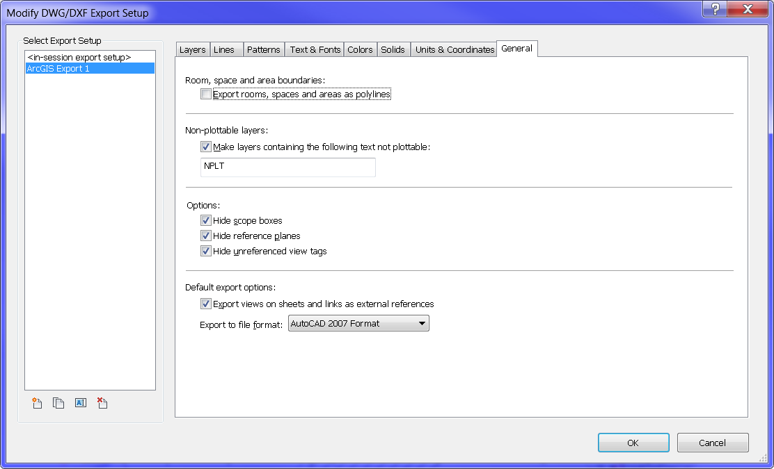
The important one here is the file format. My coworker had the best luck with AutoCAD 2007, based on the version of ArcGIS she’s currently using.
Next step, export your 2D. R > Export > CAD Formats > DWG gets you here:
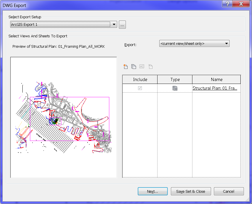
I didn’t have to make any changes. Hit Next… to export, select your file location and name. If all went well, once your GIS friend imports and tweaks, you should be able to get something a bit like this:
Now we can move along to exporting the 3D model.
My GIS coworker had the best luck with an IFC import. This exports your entire BIM model, so there’s no need to create a special view. However, you can control what exports in R > Export > Options > IFC Options:
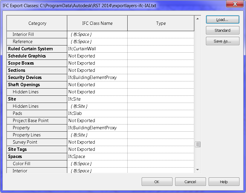
You could spend all day in there tweaking, but starting out, the default arrangement worked pretty well for us on this project. All of the settings we used for the 2D export in terms of units and coordinates seemed to carry over well to the 3D export.
Cross your fingers and head to R > Export > IFC.
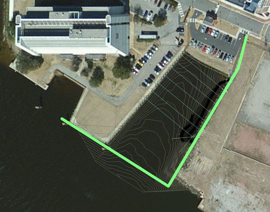
With everything already set up, my coworker was able to import the IFC to ArcGIS, and everything still projected correctly. Here’s the final result, 2D topography contours (dark) and a 3D topography mesh (light) overlaid on a satellite photo.
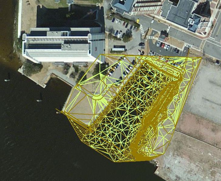
Success!