This one is brief and simple. I have six routers going right now (and a ridiculously long article still in draft explaining why), all running OpenWRT. I had them set to save logs to local thumb drives, which, frankly, was a pain in the butt. I concluded that I wanted them all logging to a single remote system for simplicity – the old EEE PC netbook that I use as a network terminal for basic maintenance. It has a good old fashioned spinning disk hard drive, and won’t suffer from a ton of log writes like the thumb drives (or heavens forbid the internal storage) on the routers would.
After going through several tutorials that were either a bit complicated or a bit incomplete for my specific use, it turned out to be obnoxiously simple to implement. I could’ve gotten it all done in under half an hour if I’d already known exactly what I was doing, and most of that time was repetitively ssh-ing into six different routers.
That said, here it is: quick, dirty, with no missing or extra steps!
Set up your log server first
My logserver is running Debian Buster, which already came with rsyslog configured with very sensible basic settings (logging to file in /var/log/, and rotation already set up). All I had to do was enable listening on TCP or UDP 514 (I’ve opened both but am using TCP), then set up some very basic filtering to sort the remote messages the way I wanted.
All changes can be accomplished quickly in /etc/rsyslog.conf. Starting at the top, we uncomment the lines that start the server listening:
# provides UDP syslog reception
module(load="imudp")
input(type="imudp" port="514")

# provides TCP syslog reception
module(load="imtcp")
input(type="imtcp" port="514")

# List of sub networks authorized to connect :
$AllowedSender UDP, 127.0.0.1, 192.168.0.0/16
$AllowedSender TCP, 127.0.0.1, 192.168.0.0/16
The last group there was added based on the recommendations of a tutorial, and restricts senders to localhost and my local network (I have hosts on five subnets, most people could be using 192.168.1.0/24 or whichever single subnet they’ve configured).
Next, near the bottom of the file, you need to decide how you want your messages stored. If you don’t change anything, they’ll be mixed into your other logs from your localhost. You can do a lot of more complicated things, but I wanted one subdirectory per remote host, with all messages in a single syslog.log. Here’s how you get that, in the rules section and above your rules for normal localhost messages:
###############
#### RULES ####
###############

#
# ADDED BY CHUCK
# Redirect all messages received from the network to subfolders first
# From example on stackexchange saved in notes.
#

$template uzzellnet,"/var/log/%HOSTNAME%/syslog.log"

if $fromhost-ip startswith "192.168." then -?uzzellnet
& stop
The template can be named anything. This test checks all log messages to see if they are from remote hosts in my local net – if so, it sends them all to a single file based on the remote hostname. The template statement must be before the test, and “& stop” tells it that any logs meeting this test should not be further processed below with localhost messages.
Obviously your log server will need a static IP to do this job. If you haven’t set one already, you can either set it manually from the server, or (my recommendation) just configure your DHCP router to automatically provision that machine with a static IP.
That’s it for configuring the server! It really is that simple. Just restart rsyslog on your server:
chuck@raul:/etc$ sudo systemctl restart rsyslog
Now, set up each remote OpenWRT host
All settings for logging are stored in /etc/config/system. By default, everything is logged to a ring buffer in memory, and lost on reboot. Not useful if something happens that causes a lockup, etc., but it is awfully handy to read from the command line when you’re already logged in via ssh, so we want to keep that functionality – messages should both be stored in the ring buffer and sent to the remote server.
In /etc/config/system, add or change the following three lines (using the static IP address you’ve provisioned for your log server):
You can leave it the default UDP if you prefer – there’s less network overhead, but most of us aren’t really hurting for network capacity. TCP is generally worth it for logging unless you really don’t care if you miss the occasional message.
Now, just restart your logs so the new settings are picked up:
Next, log a test message. It can say anything. This was the one from the last of my six routers to configure, a test machine I’m still setting up to replace one of my production routers soon:
root@FASTer2:~# logger "First test message from Faster2!"
That should produce a log line both locally and remotely. Check the ring buffer:
root@FASTer2:~# logread
Thu Dec 17 20:22:07 2020 daemon.info logread[424]: Logread connected to 192.168.1.209:514
Thu Dec 17 20:22:21 2020 user.notice root: First test message from Faster2!
Now, on your log server, you should see a new directory for your host created in your log folder (probably /var/log/ if you’re using Debian defaults). We said in rsyslog.conf earlier that the file should be in that subfolder and named syslog.log, so let’s test receipt:
chuck@raul:~$ sudo cat /var/log/FASTer2/syslog.log
[sudo] password for chuck:
Dec 17 20:22:07 FASTer2 logread[424]: Logread connected to 192.168.1.209:514
Dec 17 20:22:21 FASTer2 root: First test message from Faster2!
That’s it! We’re all set to go. You can obviously get way more elaborate than this, but a simple 1:1 replacement of OpenWRT’s default ring buffer with a neatly sorted single log file will probably cover most users’ needs.
One interest of mine that hasn’t yet appeared on this sporadically updated blog is trains. I grew up in a railroad town, with mostly railroad friends, and largely in a model train store (which also eventually became my first job at 15). It’s a hobby I’ve had neither time nor space to pursue in 20 years, but the interest is still there, and of late the bug has been biting again.
My rail line of choice has always been the Chesapeake and Ohio, and I grew up along the James River subdivision. However, some time meandering through Carl Arendt’s Small Layout Scrapbook led me down the rabbit hole to Brooklyn’s offline terminals. That piqued my curiosity, and some Google meandering lead me to Bernard Kempinski’s excellent blog post on C&O’s Brooke Ave. yard and Southgate Terminal, which I understand was also featured in an article he wrote for Model Railroad Planning 2002. To the best of my knowledge, this is the only offline terminal on C&O’s original pre-merger network.
I’ve walked the present site of Brooke Avenue yard many times myself over the years without even realizing what had been there; it’s well within my usual walking range on the (increasingly rare) occasions when things are quiet enough to take a long lunch at work. Needless to say, it grabbed my imagination, and I’ve spent the last two weeks digging up a lot of information on this facility. Very little solid information is available online, and it turns out I already have access to more offline information than most people for this site, between being walking distance to Norfolk Public Library’s Sargeant Memorial Collection of local records, and having access to a handful of old engineering records from my own engineering firm’s old surveys of the area.
Overview of Chesapeake and Ohio Brooke Avenue Yard and Southgate Terminal, 1948.
As I can, I’ll begin compiling that information here in a series of subsequent articles, linked below as I complete them.
I got into an excellent discussion elsewhere on how alternators work with multiple battery banks and isolators. It’s not completely complicated, but it takes a lot of words to try and explain and make sense. After scouring the internet for good illustrations and finding none, I ended up whipping up my own, and wanted to clean up my response afterward, expand on it, and make it a little easier to read.
The very silly TL;DR summary with multiple battery banks at different states of charge is that your auto electrical system is very socialist. “From each (alternator) according to his ability, to each (battery) according to his needs.” This is true with small tweaks whether your isolator is a relay or a diode, too.
What exactly happens when one alternator charges two batteries?
In a situation where you have an auxiliary battery connected to your starting battery with an isolator in between, how does the alternator’s regulator react? Lets assume the starting battery is at full charge (12.7v) and the aux battery is at half charge(12.0v)
From my understanding, the regulator would see a voltage of something in between the two, say 12.3v and continue to put a high voltage instead of trickle charging it to prevent damage.
Is my understanding completely off?
…
Lets say the starting battery is 95% and the house battery is 50%. In order for the current to get to the house battery, it would have to pass through the starting battery. And since the starting battery is still a lower capacity than the alternator gives, how does it not take in anything?
This question actually came up because I left the car heater vent on the lowest setting for days and didn’t realize it. Usually the dashboard shows the charging needle slightly tipped towards ‘Charge’ when I’m driving. This time, with the starting battery half drained, it was outputting much more current. What I noticed was, it also charged my house battery much faster too.
After a little discussion, I got a bit more good information from the original poster. He has an 88 Econoline with a factory battery isolation relay and alternator, so I was able to cook up illustrations that were at least reasonably specific to a particular vehicle.
I had originally wanted to grab a couple of illustrations to make it make a little more sense, but after scouring the internet to see if anyone already had the right illustrations up, no one did. No wonder nobody usually understands how this stuff works. You can find illustrations all day of battery voltage during charge or discharge, but I never did find a chart of voltage (at a specific level of charge) as it changes depending on how much current you’re putting in or pulling out right at that moment, which is what you need to understand this.
I did enough hunting to make sure my information is right, and just did up my own illustrations after work one evening.
How does each piece of the system work on its own?
Before any of this makes sense, you need to be able to see how each piece acts under different electrical loads, but there are a lot of variables that change things. These illustrations aren’t *accurate* per say to any particular setup, but they’re “about right” for the stock 2G alternator and starting battery you get in an E-150 from around 1987-1994 or so, and hopefully just good enough to explain the concept.
Alternator
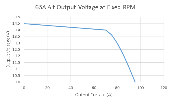
Most of the graphs for those show the max output current you can get depending on the alternator or engine speed, which doesn’t really help us much. What you really need to see is what your alternator will do at a fixed cruising speed as you increase the load on it.
Estimated and eyeballed; one day I’d like to set up a test bench to get real data for this instead.
At cruising speed, you can see the voltage output of your alternator is mostly flat up to somewhere around its rated output, and somewhere after that, as you put more load on it, the voltage it’s able to put out drops. For the flat part of the graph, the voltage regulator is cranking the field up in the alternator to keep the voltage up. Once the field is at full strength, that’s all you have, and the voltage drops quickly after that as you increase the demand for current.
This does change as your engine speed changes. At idle, with the anternator only turning about 2,000 RPM (usually about 3x crank speed), the cutoff point moves a lot farther to the left. At cruise, most Fords will have the alternator turning anywhere from 4,000-6,000 RPM, and this is probably pretty representative of that. If you’re running the engine faster, it does push the cutoff further to the right, but not by as much; you get to a point where all the resistance in the components basically wins out over spinning the alternator faster. Most Ford alternators are good for around 16,000-18,000 RPM before things start breaking.
This curve isn’t accurate or based on real test data, because unfortunately I don’t have any and couldn’t find any. This one’s based on information for separately excited alternators available in engineering texts, and modified with adding in the behavior appropriate for having a voltage regulator. So yes, I’m sure this is what the curve looks like, but at the same time, no, I’m not confident of a single exact number on this graph, since I’ve adjusted it by eyeball. Anyone want to get together and make an alternator test bench so we could get real numbers?
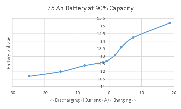
Starting Battery
Next up is what your starting battery does at different current levels.
This was the hard part to find, and I ended up extracting this info from some really good battery charts put together by a boat guy for Home Power magazine. These battery graphs are actually at least based on someone’s experimental data, so they’re a little more accurate than the alternator graph I have above. To get this graph, I essentially took the chart on the last page of the linked document, and took the values at one “slice” at a specific state of charge (90% for this first curve), then adjusted for the battery size.
Everything on that curve above changes with both how big your battery is, and how discharged it is, so I’ve made one for each of the different situations we’d need to look at to understand how isolators and multiple battery banks work together. For this first one, it’s assuming about a 75Ah lead acid battery (basically the Group 65 battery in an Econoline).
As you look to the left of zero on the bottom, that’s discharge current, with your battery supplying power. To the right is charge current, with power being put into your battery. What you can read roughly off this chart is the voltage. This chart has about the right voltage numbers for your starting battery being 90% charged, which is pretty normal for just having fired up a van that’s sat for a little while.
The least accurate part of these charts is right around 0 current. Lead acid battery behavior is very “fuzzy” in this area, and the voltage depends on a lot of other things, so don’t pay much attention to the line that connects the lowest “charging” and “discharging” currents; it doesn’t mean a lot there.
The simplest system: One alternator, one starting battery
Low Load
Now, let’s look at the first and simplest combination, just your alternator and your starting battery. Right after you fire up your van, the alternator kicks right up to 14-14.5V or so. Your van’s fuel pump and electronics are taking maybe 30A to run, so your system will probably be at around 14.2V – you have to “guess” first to figure this out, and then go back and add things up to see if your guess was about right.
What’s important to see is that your battery and alternator are tied together, so they *have* to be at the same voltage. At 14.2V, your alternator can put out about 42A, and your battery “wants” about 7A worth of charge, so 14.2V would be right if the rest of your system is demanding about 35A right then. Pretty close, but maybe not quite a good a guess as we can do, because the currents don’t quite balance out – your car and battery want 37A together, and the alternator wants to put out 42A, so we’re off a little.
I can skip a step and say 14.3V works out too high, so let’s try halfway between at 14.25V. At that voltage, the start battery wants 7.5A, and the van still wants 30A to run, and the alternator wants to put out 35A. That’s pretty darned close – within a couple of amps – so I’d call 14.25 the answer. It’s probably a little bit too precise considering how rigged up the charts are.
Medium Load
Now with that simple one alternator/one battery combo, let’s crank on the headlights and turn the fan on low; now we’ll say we’ve raised our load from the van to 50A. Let’s guess 14.1V for the system voltage. Looking at the battery chart, the battery charge current is probably going to drop to more like 6.5A at that voltage, so your total load is now about 56.5A. Your alternator graph says it’s putting out about 56A at that voltage, so our guess was good! 56A coming out of the alternator will split into about 50A going to the van and 6A going to the battery.
High Load
Okay, time to overload the alternator. Crank the heat on max (those blowers draw about 20A on max), turn on the rear air, and maybe heated seats. Flip on the wipers, get everything going. Now we’ve got about 90A of demand in the system. That’s way more than the alternator can put out by itself at above 12V, so if you trust the slightly fictional chart I made, your alternator can only put out about 11.5V at that load.
Battery to the rescue! It’s still connected, and if it were actually at 11.5V, it would really be putting out some juice! What’s really going to happen is that the system is going to settle at whatever voltage the output current from the battery and the alternator add up to 90A.
Looking at the chart, that looks like about 12.4V to me. At 12.4V, your alternator can still crank out 83A, and your battery is going to put out the remaining 7A.
The Simple System TL;DR
I picked the simple situation first because this one has to make sense before you can understand what happens when you throw in a second battery bank with a different charge. In this simple example you already have two things that can put out power (alternator and battery) that have to “decide” how to share the load. The thing is, it’s not really so much a “decision.” Each thing has it’s own natural behavior that the chart tries to make sense of, and the system has one “natural law”, which is that the voltage for all the pieces we’re looking at will always be the same (because they’re directly connected). Hence, the alternator and battery will increase or decrease output until the voltage stabilizes between them. It’s a bit of a physics balancing act.
Adding an AUX/House Battery Bank
Low vehicle load, 50% Aux battery charge
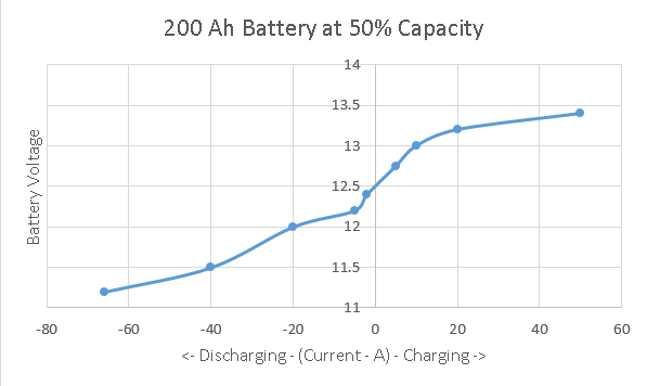
Now, let’s go back to the first example where you’ve just started the van and have a reasonable 30A system load, but now we add in your house batteries. Let’s say your battery bank is 200Ah, equivalent to almost three of those starting batteries in size – I want to exaggerate things a little so it’s easier to see the effect in the different charts. Your battery bank is only 50% charged when your isolator relay connects it to the alternator and starting battery, so its chart looks like this.
The shape is really similar, but the currents are much bigger (because the bank is bigger) and the voltages are lower (because the bank is half discharged). Your van’s system still wants about 30A to run its own stuff.
So now, with that isolator relay connected, the “all the voltages are the same” law applies to all three pieces. To figure out what it’s going to do, I have to guess a voltage again to start. I can make an educated guess and say maybe the system will run at 13.5V, which looks pretty close. Let’s see, at 13.5V our alternator puts out about 76A, and our demand is 30A (from the car’s electronics) plus about 3A (what the mostly charged small battery wants at that voltage) and a whopping 65A that our hungry battery bank wants at that voltage. That’s a total load of 98A, way more than the alternator is putting out, so I’ve obviously guessed wrong!
If I try again it comes out closer – At 13.4V, the load is 30A car, still about 3A starting battery (too small a change to tell from the chart), but down to about 40A on the battery bank. The alternator can put out just a few more amps, too. So the load goes down to 73A, and the alternator’s capacity creeps up to maybe 77. Basically, we’re about there; 13.4V is about as accurate as we can get with these charts.
With that example, you can really see how the power gets split between the two battery banks. Your starting battery doesn’t want much; it’s too full to take much more charge at that low of a voltage, and the voltage is still too high for it to discharge at all. Meanwhile, your aux battery bank is hungry, and it’s just going to suck current in until it drops the alternator’s voltage down to a level where it’s being satisfied. As the current goes up, the alternator’s voltage drops, and as the voltage drops, the aux battery’s “hunger” drops, so they meet in the middle.
Low vehicle load, 50% Aux battery charge
Now, to see what was going on with your rig the other day when your aux bank was really down, here’s a curve for your aux battery at only 20% charge.
This is enough of a difference to start to suck juice out of your starting battery, just like you saw, though not much at all yet.
I’m going to guess 12.7V first. At 12.7V, your alternator is putting out about 82A, your start battery is actually putting out about 1A. Your van still wants 30A to run, and your aux battery wants to suck up a full 50A! That’s probably a pretty good guess on the voltage, we’re within a couple of amps of everything adding up. 83A or so from the alternator and start battery, and 50 of it going into recharging the auxiliary bank.
You can see where even small changes in my guesses on making those graphs would make it draw harder from your starting battery.
If your aux was less than 20% charge left, you’d definitely pull a lot harder from the starting battery, since your alternator is completely maxed out.
My “alternator curve” could easily have been generous for that alternator over 70A, too, since I just cooked up that part of the curve “by eye” until it looked right. Unlike the batteries, I don’t have good hard data for that one, just enough basic knowledge of how it works to cook up a chart.
The smallest increase in load from the van itself is going to come almost straight out of your starting battery now, with house battery charge current decreasing. The alternator is almost completely maxed out, so if you turn out the heaters for 10A (for 40A total for the van), the voltage drops a tiny bit to 12.68V, your alternator still produces about 82A, the starting battery puts out about 2A, and your aux charge current drops to only 44A (for an 84A total load). Doesn’t sound like much, but the ammeters in the Ford dashes are actually really sensitive, and you’d definitely see that as a very noticeable needle twitch.
On the other hand, this goes to show why you shouldn’t worry too much about a relay isolator causing your aux batteries to “drain” your start battery when the car is running. You have to really drain down your house batteries before they even start pulling any current out of your start batteries, and even then, it’s a tiny trickle.
At the same time, you can see how recharging the house batteries from a really low charge really works the snot out of the alternator. Not a good part to cheap out on.
What about a diode isolator?
A diode isolator does change things, and not always in a good way. It does guarantee that your house bank won’t pull charge directly from your starting bank when you’re running. However, as you can see from the examples above, that’s not really a big risk even with a simple relay.
What a diode isolator definitely does is change the shape of the alternator curve. Diodes have what is called a “forward voltage drop” when they’re working. This is basically a fixed voltage loss whenever current is flowing. I understand for most alternator diodes this is about 0.9V.
To compensate for this, the “voltage sensing” wire for your voltage regulator is still attached at the starting battery, on the downstream side of the diode (do not attach on the aux battery side instead). If your regulator wants 14.2V, it’s going to crank the field on the alternator higher, until the alternator is putting out 15.1V. This will produce 14.2V on the downstream side of that diode.
This affects alternator performance three ways:
It adds load to the alternator. If you’re producing 50A, you are losing 45W crossing the diode, so that’s another 45W the alternator has to put out. This means your alternator will always run a little hotter.
It reduces the alternator output where the regulator maxes out. Because it’s taking extra field strength to supply the extra 0.9V, your regulator will run out of the ability to add extra “kick” at a lower output current, so you “fall off” the flat part of the curve earlier.
You lose voltage everywhere above that flat spot for a given current, so your charge performance when the alternator is maxed out decreases very measurably.
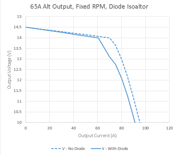
I’ve made another rigged up chart that shows this behavior. The overall curve isn’t the most accurate, but the difference in performance is pretty on-the-mark.
Ouch!
The original alternator curve is dotted. I’ve stretched the graph a little taller to make the differences easier to see. It’s a little squiggly from 14 to 13V, but overall it’s about right.
As you can see, there’s not much difference when you’ve got a low load. However, once you’ve maxed out your field, whoa! What a difference. The alternator that was rated at 67A would probably be rated at about 58A now if you used the same criteria. You lose almost 5A all the way through the range. All your lost power is going into the 50W+ or so that your diode is eating.
This is why I like isolator relays. Even at the very high currents you get recharging a 200Ah bank that’s drained way down, I can get a continuous duty solenoid that will handle the current for $40 tops. I’d much rather spend the extra money you’d pay for a diode isolator (about $35 extra minimum for this alternator size) toward a much better alternator instead.
So what’s really going on here?
Nothing in the system really knows how to distribute the electricity, each piece just has it’s own performance characteristics, and the system will “balance out” naturally to whatever voltage makes the available supply (from the alternator) meet the demand (from the car electronics, and the two battery banks).
Plus, diode isolators are the devil! (Your mileage may vary)
I thought I’d add in an update on the (hopefully) final resolution of last year’s 300 I6 distributor trouble. I had one more failure, not long after my last post, and it was a particularly inconvenient one.
On 6/13, the roll pin for the distributor gear fatigued. Thankfully, it didn’t completely shear, but it did lose a layer on both ends, which means I lost about 20* of timing and all power. Unfortunately, it did this at 70mph, on a 95*F day, in the left lane, passing a semi on the interstate while pulling a loaded stock trailer, with a truckload of our good working dogs, 130 miles from home. I can think of less pleasant breakdowns, but not too many. This represents about 2,000 miles at most on this particular distributor install.
Thankfully, we were only twenty miles from a friend’s farm, and she came to our rescue. We left our rig and stock at her place overnight, and came back the next day with a couple of spare roll pins and enough tools to replace one roadside. We carefully limped everything home, and I started doing a postmortem.
My final conclusions on the problem came down to:
Never re-use a roll pin in a distributor. The pin that sheared was the original pin from the Rich Porter. It may have been low quality to start with. Use an upgraded new pin every time you pull one out.
You can’t get a properly made 300 I6 distributor, remanufactured or aftermarket. You’re going to need to do some careful re-engineering to reliably use any replacement you get.
For the love of all that is holy, if you have a factory distributor that isn’t absolutely FUBAR, don’t replace it! I’ve never, ever personally had a distributor failure on a Ford that still had it’s factory distributor and where no one has screwed with it. Maintain or repair as needed, but any replacement you get is likely to be worse than the broken unit you’re pulling. I have no idea why the original part was swapped out on this engine before I bought it, but I’d wager good money it was because someone was throwing money and parts at a problem that had nothing to do with the distributor.
Here’s why your new or reman distributor is most likely to experience roll pin fatigue failures. The distributor gear should be a press fit on the shaft. That press fit should be what’s carrying all the load, and the pin should basically be a safety device.
However, the machining on new distributors is crap, and you can almost bet any reman you get will have had a failure which spun the gear on the shaft (my reman NAPA Echlin arrived that way). Either way, every distributor I’ve put in during this saga has had a distributor gear I could turn on the shaft by hand without the pin installed. The combo that fatigued on me was the loosest, and when you combine it with re-using the cheap pin that came from the RichPorter, you can see why it died. In fact, when I re-pinned the NAPA and drove it carefully home, the pin I popped in (which was the original NAPA pin) had already started to fail when I pulled it out that evening – under 150 miles.
My solution to this has so far worked for six months and about 10,000 miles. First, I bought a 100 pack of brand new, high strength roll pins. They are about 30% stronger than the standard roll pins of this size, and probably almost double the strength of the off brand pins that came with both the Rich Porter and the NAPA reman.
Second, I went ahead and bought a brand new Rich Porter, with the intention of immediately tearing it down. They are almost the only game in town in terms of new 300 I6 distributors, and if I’m going to start with junk either way, I’d rather it be new junk with a lifetime warranty. Upon arrival, I immediately pressed out the crappy stock pin, pulled the gear (which was loose, but a lot better than the NAPA unit started out), and removed enough end play shims to get the end play up to 0.030 where I wanted it. I really didn’t want a repeat performance of the original Rich Porter getting too tight and popping it’s hall plate off the top splines, since that was the only problem I actually had with the original Rich Porter.
After a careful break-in and timing set, that combo has now been in for about 10,000 miles, including plenty more miles on the interstate with the stock trailer. That means this has also lasted at least 6,000 miles more than any other distributor we’ve had in it since purchase last year.
I was also determined not to get stuck by a failure again if I could help it. I replaced the already fatiguing “new” pin in the NAPA with a new high strength one, and have that crap distributor and enough tools and spare pins to change and repair it roadside sitting in the van’s toolbox. I’ve got that routine down to about 20 minutes, which is a lot faster than the tow truck showed up. I just checked the pin by feel last Friday (the shaft movement feels “soft” when they’re starting to break), and so far it still feels good, with no measurable timing loss with the light either.
I’ve seriously considered selling these nice little pins as singles or small packs on eBay or Amazon. At $2 a pin plus the cost of a stamp and an envelope, they’re a lot cheaper than the 100 pack I had to buy, and cheaper than the single pins anyone else is selling online (mostly $5 and up). You can’t get them in quantities less than 100, and I hope to never use up the other 99. They’re high strength steel and have a minimum double shear break strength of 2,000lb, which means they are good for 44 ft-lb for the distributor gear in a 300 or 351W, or 39 ft-lb in a 302 (smaller shaft). I’ve got the info on them if anyone wants them, or would probably mail a few for a couple of bucks plus postage.
Here’s hoping this helps someone else out, too. I’ll update again if I ever get another failure with this. Meanwhile, I’ve seriously started considering getting my own shafts machined so I can actually get a proper fitment. Most likely I’ll probably end up swapping in the spare 302 I have instead, though. The 300 isn’t the best in the world right now with a stock trailer at 70.
I got involved in a discussion elsewhere on this topic, and wanted to share my response here as well. This is meant to be a solid explanation in layman’s terms, for those who don’t want to dive down a big physics and thermodynamics rabbit hole!
While I’m an automotive engineer I’m ashamed to say that I still don’t really understand the relationship between displacement and power/torque produced. While I assume that the difference between the 1000+hp – 8l engine in the Veyron and the 645hp – 8.4l engine in the Viper is mostly determined by turbos I would prefer a more detailed explanation.
Leaving out for a moment questions of efficiency, turbocharging, and a lot of other smaller factors:
Torque is most proportional to displacement. This is mostly a matter of how much fuel you can burn per cycle of the engine. Torque is a force, and applies to questions like, “how heavy a car can I push up this slope?”
Horsepower is proportional to the product of torque and engine rpm. There’s a constant in the equation, but otherwise it’s a direct relationship. Power applies to the question, “How fast can I push this 4000lb car up this slope?”
Everything else is just a factor that modifies those two variables. Let’s take the steady-state example of a truck climbing a steady grade at a steady speed – it’s actually simpler to understand than everyone’s favorite “drag race” example. Want to increase the amount of load you can carry up the hill at a given speed (increase the power)? Here are the ways you can do it:
Make the engine bigger. If everything is proportional so that your efficiency is the same, your torque will go up proportionally as well, because you’re ingesting more oxygen and burning more fuel. This means your power will also increase proportionally. More torque at the same speed (more power) means you can pull a heavier load up the hill.
Spin the engine faster for the same road speed (RPM). You’re still making roughly the same torque at the engine, but to maintain the same road speed, you will have had to change the axle/transmission gearing. This gives your same engine torque more “leverage” on the road. This example both shows the difference between torque and power, and shows you why it’s power that matters for climbing hills. Looking directly at the power really tells you what your engine can do at a given road speed once you’ve factored in all the gearing – it simplifies everything (better tool for analyzing that type of job).
“Fake” making the engine bigger. You can do this with turbocharging, supercharging, nitrous oxide … your choice. Either way, you’re using an external component to force additional oxygen and fuel into your engine, faking the behavior of larger displacement. The result is more power. This solution will almost always be more efficient for some operating conditions and less efficient for others, so you get to pick where you gain and lose economy, too. You have to do more work “stuffing” in the extra air, which reduces efficiency, but it can let you tune for better efficiency when you don’t need full power. Ford Ecoboost is a good example of this idea.
Improve overall efficiency. You can do this by increasing compression, tweaking your spark timing, mechanical/frictional tweaks, anything that gets more of the energy from your fuel to your tires instead of going out the tailpipe and radiator. You tend to be pretty limited by your fuel quality here compared to the first three options.
Improve efficiency at the engine speed you’re operating. Change your valve timing. Here, you’ll trade better efficiency at the RPM you care about for worse efficiency elsewhere. Your limit here is that you still have a “peak” torque value proportional to displacement, which you can move around with valve timing but not really increase. Assuming you don’t change your gearing (RPM) at the same time, once you get to the point where your peak torque is at the RPM you’re climbing the hill, you’ve gained all you can with this option.
In short, power is everything. Torque only really matters in that you’d like most of it to be “well distributed” across engine RPM, instead of very concentrated in a narrow band – this just makes your engine more versatile and nicer to drive. However, for pulling a hill, etc, the question of “not enough torque” is always solved by “more gear”, because the power is the same either way; that power is really just a matter of how much oxygen you can stuff in, and how much heat you lose from there to the tires.
For a good comparative example, consider the difference between the 110ci engine in a Miata and the 300ci engine in a mid-90’s Ford. I have both. Both make roughly the same HP, plus or minus a few – around 140.
The Miata has high compression, good mechanical efficiency, and all of its variables (valve timing, etc) are tuned to maximize the available torque and power from 5,000 to 7,000 RPM. It’s torque curve is very peaky, maxes out at about 115 lb-ft, and below 3,000 it’s essentially worthless. This is okay for acceleration, because everything is lightweight, and the car has very steep axle gearing (4.56:1) to try to keep it where it makes some power. However, you’d never want to tow anything with this engine, because the high RPM and compression really limit reliability if you needed to make the full 140 horsepower long enough to, say, climb a 10 mile hill, something you’d never need in a 2500lb car even at full speed. You need five (efficient, manual) gears at a minimum to keep this little engine where it will get out of its own way, and you’re shifting constantly in hilly terrain and traffic.
In contrast, the 300 is in a 90’s van with a three speed automatic, probably the most reliable but inefficient transmission Ford ever produced. Because of the massive energy-suck of the transmission, considerably less of this engine’s power gets to the road than the Miata’s. It’s in a vehicle that weighs double what the Miata does, and which will happily tow its own weight – so this engine is happy moving four times the load of the Miata. Why? Rather than focusing on a narrow “happy” spot, the design focused on distributing it’s torque out well. It doesn’t have overwhelming “go” anywhere, with only 260 ft-lb of peak torque limited largely by very low compression compared to the Miata; at the same time, what “go” it has is available everywhere (over 200 for almost the entire operating range). It makes its maximum power at only 3500 RPM, which it will happily do all day long, on crappy fuel, in lousy, hot, humid weather. Because the torque curve is so flat, you almost never find yourself shifting for any hill but the most extreme. It’ll never get anywhere as fast as the Miata, but it will go everywhere with extreme reliability doing four times the actual work, strolling along like a big, dopey draft horse.
You can dive down the rabbit hole all day with the hundreds of smaller variables that affect torque and power, but sometimes the basics are better summed up with no math and a little example or two. If nothing else, hopefully this version was entertaining.
On the other hand, a postmortem on the pair of dead distributors, and a review of the Ford documentation on distributor drive gears, has shown me a likely common cause for both failures.
Ford indicates in the linked document that “very little or no shaft endplay… has been found with new and remanufactured distributors. Improper endplay may force the gear against the support in the block or hold it up off the support, causing damage.”
Before I began the repair, I checked the distributor shaft end play on both the NAPA with the failed gear, and the Rich Porter with the failed rotor plate (after pressing it back on). Both were in the neighborhood of 0.010″ to 0.012″, which is substantially less than the 0.024″ to 0.035″ called for by Ford.
The distributor is a steel shaft in an aluminum housing. As the assembly heats up, the aluminum grows more than the steel shaft, and the end play measurement decreases. If you have too little end play, the end result can be that your clearance goes to zero, trapping the housing between the rotor plate and the drive gear. This could easily either press the rotor plate off its splines, or in the case of the NAPA unit, put so much load on the softer drive gear that it wore out almost immediately.
I needed a rapid fix, and swapped the perfectly good steel gear from the failed Rich Porter onto the NAPA distributor. Since I had to re-drill the roll pin hole in the process anyway, it let me set my own clearance, and set it properly. I set the clearance to 0.032″, and so far I’ve had zero issues since the repair (approximately 1000 miles).
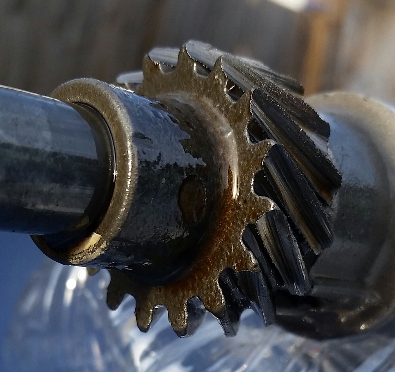
As the NAPA gear wore, it manifested in progressive loss of base timing as the teeth wore away. When I sorted out the cause of the problem I was having (misfire, loss of power and fuel economy), I measured a loss of 6º of base timing on the #1 cylinder. However, #1 was one of the least worn teeth, visible at the bottom in the photo. Based on the wear in the other teeth and the difference in rotational play with the distributor still installed, I was losing at least 10º on the #6 cylinder, where I was seeing the most misfires.
Currently, after a timing re-check yesterday, I’ve lost less than 1º of timing since I set it after breaking the gear back in. Actually, I’d say zero, but my timing light just isn’t that accurate.
As a note on the Ford 300 inline six, there’s very little drawback to setting your distributor shaft end play high. Unlike the V8 engines, the distributor rotates clockwise from the top, and as you can see from the wear on the gear, that means the gear rides up on the plain bearing surface at the bottom of the distributor housing, not on the gear support block inside the engine block. Because of the load of the oil pump, the gear will stay up against the housing steady as the engine is running, so you won’t have a timing variation. A bit more end play just puts your rotor a tiny bit higher in the cap – nowhere near enough to cause an interference.
I experienced a new-to-me form of failure a week or so before Christmas, and thought I’d share the details, since even a pretty detailed Google hunt failed to turn up any other account of this problem.
The vehicle is a 1996 Ford Econoline with a 300 I-6. After driving around perfectly for an hour, it suddenly lost most of its power mid-drive, running smoothly but unable to exceed about 10mph. Manual shifting of the C6 proved we still had both first and second, and it still started acceptably (if weak), with no sign of engine shakes or cylinder misfires. A quick roadside diagnosis showed no new codes, nothing out of the ordinary in the OBD II data stream, and a look at the distributor indicated it was still tight and hadn’t shifted from the previous owner’s paint mark (which was correct, I’d checked timing in November after purchasing it).
After a tow home, I began diagnosis. After eliminating some of the other basics, I got the timing light out, and found it was running with a base timing of about 20* ATDC. Loosening the distributor hold down and twisting in about 30* more timing immediately removed the symptoms. Then, it was time to find the cause.
With a loose hold down bolt ruled out, the usual suspects would be the timing set, the distributor gear at the cam, or the shear pin that holds the gear to the distributor shaft. A dead timing set or stripped distributor gear usually mean no start, not timing slipped. I suspected the shear pin might have went, with the gear just tight enough on the shaft to have “stuck” after losing some timing.
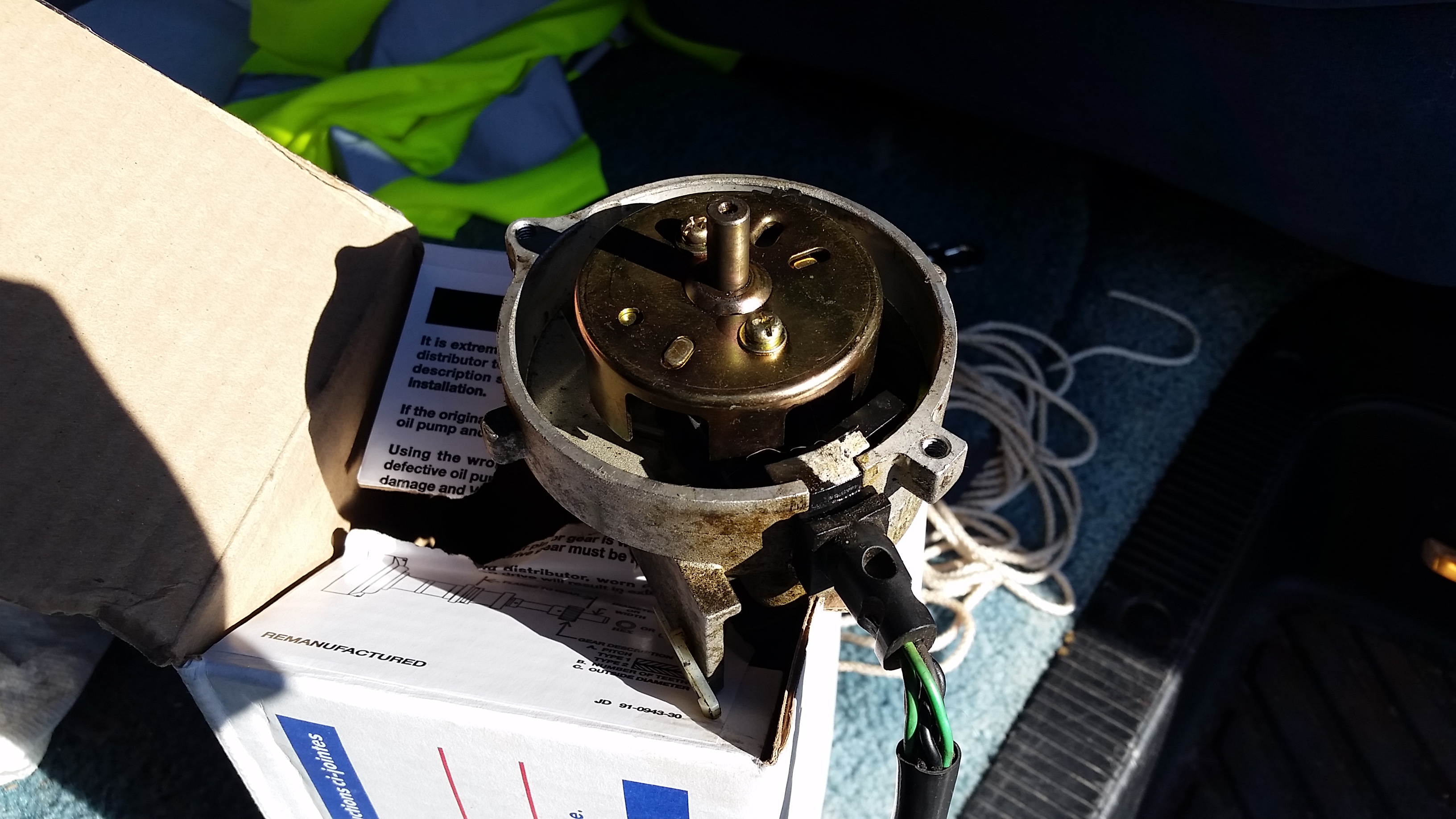
I pulled the cap and rotor, and everything looked normal at first glance. Here’s a shot after having pulled the distributor.
This is the failed distributor, which looks innocuous with the shutter wheel still on the shaft.
However, once I grasped the shutter wheel and gave it a bit of light torque, I immediately felt a “notchy” click, and was able to rotate it. The possibility of a magic “half-stripped” distributor gear went briefly through my head, but it didn’t take long to realize the distributor shaft wasn’t turning at all. In fact, the shutter wheel popped right off in my hand.
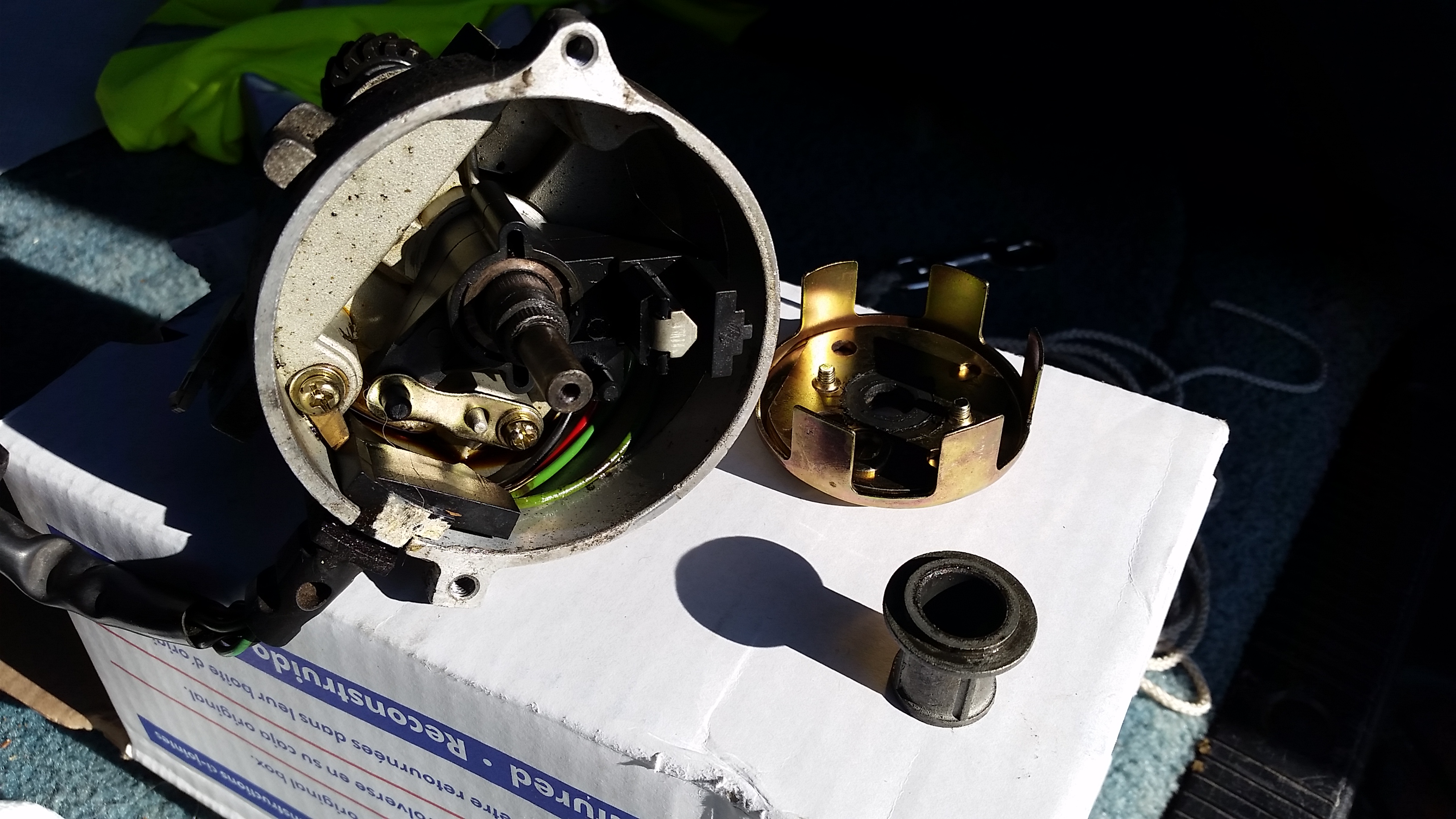
This shot shows the failed component. Notice the stripped splines where the TFI shutter wheel should press onto the shaft.
At that point, it was obvious what had happened, though I still can’t point to why.
I pulled the distributor, verified the gear and shear pin were in fact fine, and popped in a NAPA reman, which was the only thing I could get locally that day. The failed unit was a Richporter Technologies, and the NAPA is a reman Motorcraft.
I still have no clue why the original distributor was replaced by the previous owner – I’ve never had an original actually fail, and this engine has pretty low mileage for a 300. I’m guessing his mechanic swapped it in when they were trying to hunt down a SPOUT circuit error, which I suspect is part of why I got this van so cheap. That was something simple I fixed five minutes after we bought it – a slightly loose terminal at the back of the SPOUT connector. Haven’t had a single real issue with it other than the SPOUT issue and the newly failed aftermarket distributor.
Have an axle with an unknown ratio that you’d like to identify? Want accurate results? Here’s a simple, dead accurate method that will give you results on any rear wheel drive axle (or any front axle for a four wheel drive), as long as the axle in question is driven by a driveshaft. Sorry, front wheel drive folks, you’re generally out of luck on this one. This is a single-person technique. Helpers are not required, though one does make the counting a bit quicker.
Tools required:
Chalk, crayon, or paint pen
Jack
Jack stands
Safety:
I make the general assumption that you already know to follow all the necessary safety techniques. If you don’t already know how to do anything required here safely, find a friend to learn from, or another source of knowledge. General work safety practices for cars abound on the internet. Hence, work at your own risk.
Steps:
1. Determine if you have an open differential, or a traction aid (limited slip, locker, etc.). If you don’t already know, here’s how. Jack up the axle and put both sides on stands, so both wheels are off the ground. Leave the transmission in park or in gear (manual). Rotate one wheel by hand, while watching the opposite wheel. If the other wheel rotates easily in the opposite direction, you have an open differential. If there is resistance to rotation or no rotation, you have a LSD or locker. To verify a traction aid, place the transmission in neutral, and both wheels should rotate together when you turn one by hand. I’ll note differences in later steps between open and traction aid techniques.
2. LSD/Locker: leave the car on the stands. Open diff: lower one tire to the ground, leave the other on a stand.
3. Mark the tire and driveshaft. Put one mark on the tire sidewall where you can easily see it, and another on the driveshaft near the axle. You’ll need to be able to see both from where you’re working unless you have a helper, so they should both start out facing you. If you have a lot of tire clearance to your fenders, it’s often easiest to start with the marked spot toward the ground, and a block of wood or rock to use as a reference point. You want to be able to count tire turns to within a few inches of your starting point; more accurate than that won’t really be necessary.
4. Now, you’ll need to rotate the tire while counting turns of the driveshaft using your mark. Rotating forward or backward doesn’t matter. Turn the tire 10 turns for an LSD/Locker, 20 turns for an open differential. When finishing, try to count your last driveshaft turn to the nearest 1/4 revolution.
5. Divide the number of driveshaft turns you counted by 10 (same for both LSD/Locker and open). That’s your gear ratio.
Examples:
You determine your pickup has an open diff, so lower one tire to the ground. You turn the tire 20 turns, and count 35-1/2 turns of the driveshaft. 35.5 / 10 is 3.55 – a common stock gear ratio for Ford pickups.
Your car has a limited slip, so you leave both tires up. You turn the tires 10 times and count about 27-1/4 to 27-1/2 turns. This will be either 2.73 or 2.75 depending on your axle make and what ratios are available.
The last number is always a bit of a fudge with this method, but always close enough, as you’ll basically never encounter a single axle make that has two different ratios available that are so close. You can always count on the first two numbers, such as 2.7x and 3.5x, being dead accurate, and that’s always close enough to identify the exact ratio once you know what axle family you have. For instance, with a Ford, the 2.7x example is going to be 2.73 if you have an 8.8″ or 7.5″ axle, or 2.75 if you have an 8″ or 9″ axle.
I’ve used this method many times over the years, since it’s dead on and works great whether the vehicle still has its stock gears or not; axle tags are only useful if no other previous owner decided to regear. I also take a crayon with me any time I’m headed to a junkyard or to purchase an axle, for the same reason.
This is an issue I ran into at work over the past week. We needed to get topography from a project I was working in BIM into ArcGIS for our GIS modeling folks. Days worth of googling revealed absolutely nothing useful – it was evident that someone had kludged together a few successful techniques back in 2009 and 2010, but there was absolutely nothing recent. Either BIM-based engineers no longer needed to get their info out to big-world GIS folks (unlikely), or no one who’s solved this problem since 2010 has taken the time to document it where the rest of the world can find it. It turns out the entire process takes about 15 minutes, but sorting out the process can take a week of frustration based on the information that’s readily available.
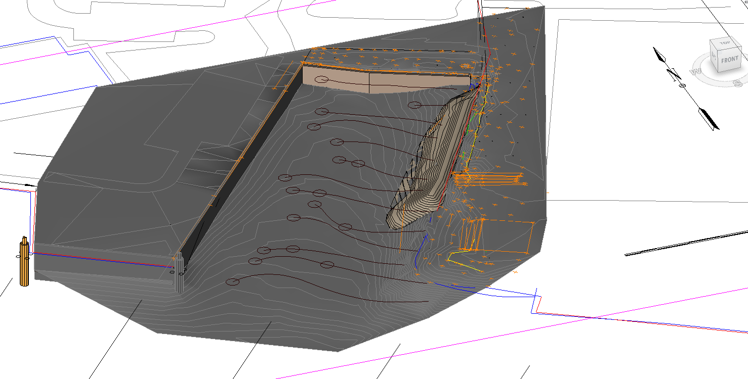
The problem: A Revit 2014 model, consisting mostly of site topography with a few “building”-like features. The model is built on a 2D survey with a vertical datum of NOAA NOS MLLW, and a horizontal datum of Virginia State Grid (South Zone) NAD 83. None of that really means anything electronically to anyone who isn’t trying to get a conversation going between BIM and GIS. The relevant part of the model in Revit looks like this, in 2D and 3D:
Example File – Revit 2D
Example File – Revit 3D
It’s important to note before we begin that you may need to export in both 2D and 3D to get your GIS coworkers everything they need. The 3D export will carry your model elements over, but they will often need contour lines for your topography, and contour lines are a 2D only element. The only way we’ve found to get both your elements and contours into GIS is by exporting a 2D contour set to go with the 3D model.
Revit has a lot of user confusion due to multiple coordinate systems. There’s an “internal” system that the user never sees, a “Project Coordinate” system controlled by the Project Base Point, and a “Shared Coordinate” system controlled by a Survey Point. Revit has limitations on how far parts of the model can lie from the internal origin, so it’s best to keep your Project Base Point somewhere near most of your actual model. In our case, the Project Base Point (and internal origin point) is a circular symbol to the left of the 2D, near the corner of a large flat spot that’s actually a helipad. We can’t move the Project Base point to our survey grid origin, since that’s 12 million feet to the west and far out of Revit’s comfort zone.
What we can do is put the Survey Point out there, thus setting the Shared Coordinates to match NAD83. This seems to work just fine. My file has a 1000′ grid of coordinates which are just out of view in the 2D above. To set the survey point, find the nearest convenient known point, and use the following tool: Manage tab > Project Location > Coordinates > Specify Coordinates At Point. You’ll need to use this tool once each for Northing and Easting.
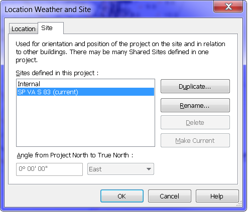
What if you’re already using Shared Coordinates to coordinate between several discipline files? In that case, create an alternate Location. Go to Manage tab > Project Location > Location > Site:
Revit Site Dialog
Click Duplicate… to make a new site, give it the name of your datum, and make it current. Now, you can go back to moving the survey point, and you’ll only affect the survey point for this saved Site. Once you’re done exporting, go back to this dialog, make your previous coordinate set current, and you’re back as you were.
Next, let’s export the 2D first. 2D exports are per view, so you’ll need to create a view at 12″:1′ scale containing exactly what your GIS team needs to see. Use VG to turn off everything extraneous, and set your crop region to exclude the large area of survey you might have in the file outside your project area.
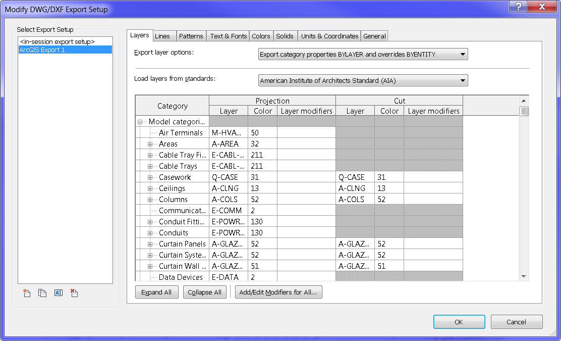
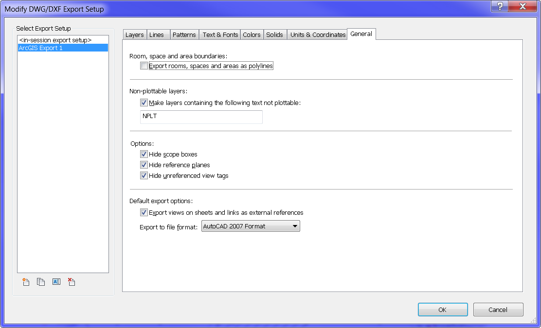
Now, we need to set a few options. Head to R > Export > Options > Export Setups DWG/DXF (in my case at least – my GIS coworker knew she could work with DWG data to get the results she needed) to set up your 2D export options.
Revit Export DWG Setup Dialog
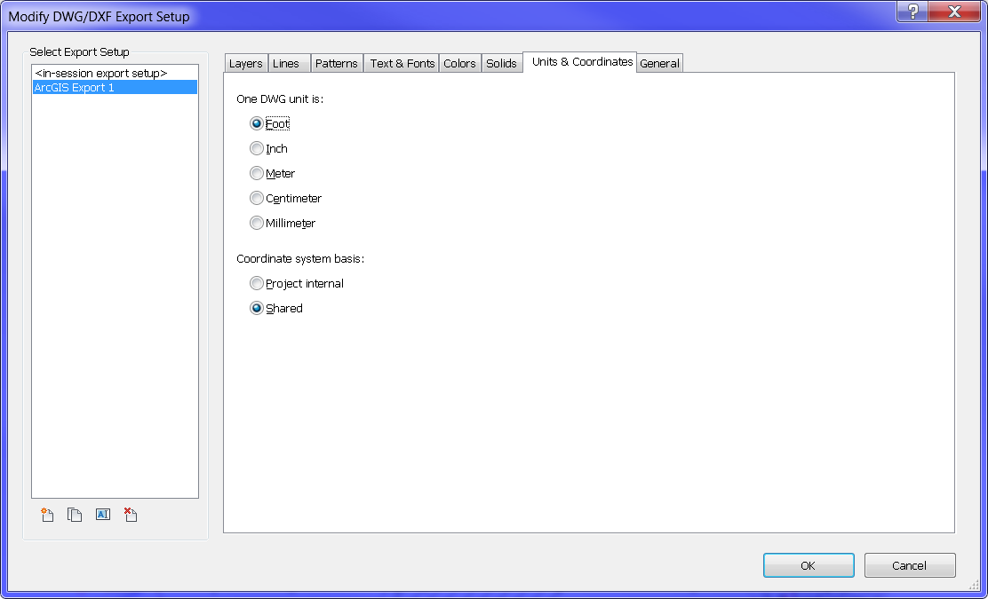
You could obviously spend half a day in here tweaking colors, layer names, and lineweights, but your GIS folks can override all that when they import anyway. The only important things to change are all buried in the depths of this dialog. First, hit the Units & Coordinates tab:
Revit Export DWG Setup Dialog – Units Tab
Change the DWG unit to Foot, and the Coordinate system basis to Shared, as shown. Our first attempts at this had the 2D importing at 1/12 scale, hundreds of miles away – these settings fixed that. Next, go to the General tab:
Revit Export DWG Setup Dialog – General Tab
The important one here is the file format. My coworker had the best luck with AutoCAD 2007, based on the version of ArcGIS she’s currently using.
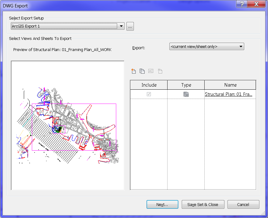
Next step, export your 2D. R > Export > CAD Formats > DWG gets you here:
Revit DWG Export Dialog
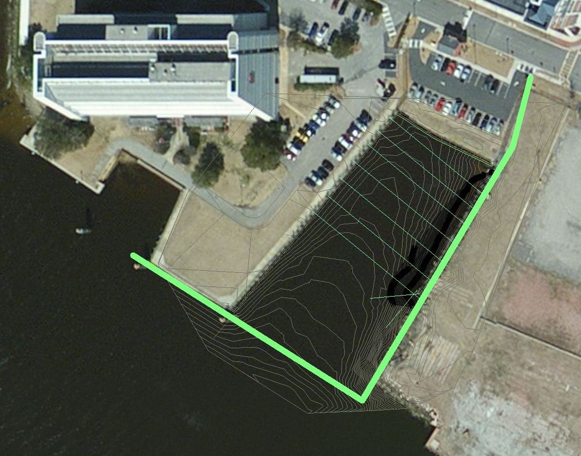
I didn’t have to make any changes. Hit Next… to export, select your file location and name. If all went well, once your GIS friend imports and tweaks, you should be able to get something a bit like this:
Revit-ArcGIS Example – Resulting 2D
Now we can move along to exporting the 3D model.
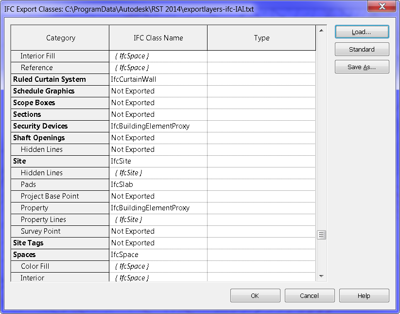
My GIS coworker had the best luck with an IFC import. This exports your entire BIM model, so there’s no need to create a special view. However, you can control what exports in R > Export > Options > IFC Options:
Revit IFC Options Dialog
You could spend all day in there tweaking, but starting out, the default arrangement worked pretty well for us on this project. All of the settings we used for the 2D export in terms of units and coordinates seemed to carry over well to the 3D export.
Cross your fingers and head to R > Export > IFC.
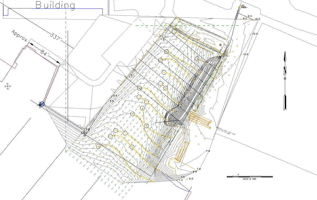
With everything already set up, my coworker was able to import the IFC to ArcGIS, and everything still projected correctly. Here’s the final result, 2D topography contours (dark) and a 3D topography mesh (light) overlaid on a satellite photo.
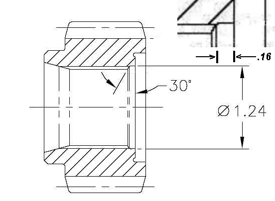
Using a non-IRS limited slip in a 7.5 or 8.8 Ford IRS axle requires the builder to choose between leaving out the axle retainer clips, or machining the differential side gears to accept them.
For those who want to keep their retainer clips, I’ve come by the following diagram for machining the side gears:
Machining Differential Side Gears for the Ford 7.5 and 8.8 IRS
I originally found this drawing on TCCOA in a post here, courtesy of 392Bird. No idea where it originally came from.
The side gear in the drawing is straight cut, unlike the gears used in the Trac-Loc, but that doesn’t really matter. What’s important here is the bevel machined between the inboard side of the splines and the gear face for the c-clip. This bevel will allow your IRS retainer clip to compress, so that you can remove the half shaft without having to disassemble the center section to compress the clip.