Automatic Autossh Tunnel under Systemd

It took me half the afternoon to figure out how to do this with all the bells and whistles (mostly a learning experience on systemd), so I’d better write it down! Meanwhile, it took me at least a dozen reference docs to piece it together, because autossh has pretty brief documentation.

Edit 2021-03-27: One thing in the original version of this article that didn’t work as intended was keeping the systemd unit file in a different location and linking it where it needed to be. That turns out not to work right under reload. Further info below.

I had a remote server running a mail forwarder which is password protected but exposed, yet I was only using it from devices within my LAN. That’s not only not ideal, but a smidge less reliable due to various odd properties of my LAN (with regard to WAN failover behaviors), so I wanted to move this traffic into an SSH tunnel. My local tunnel endpoint would be a Debian 10 (Buster) machine that is fully within the LAN, not a perimeter device. I want this connection to come up fully automatically on boot/reboot, and give me simple control as a service (hence systemd).

Remote: an unprivileged, high port PPPPP on server RRR.RRR.RRR.RRR, whose ssh server listens on port xxxxx.

Local: the same unprivileged, high port PPPPP on server LLL.LLL.LLL.LLL

My remote machine was already appropriately set up, all I needed to do was add an unprivileged user account to add this connection. In the code below, you’ll see the account name (on both the local and remote servers) is raul, which is also the local server’s name on the network. Substitute your account name of choice wherever you see this. Before beginning the real work, you need this account set up on both machines, with key based authentication (with no pass phrase). Log into the remote machine from the local account at least once, to verify it works with the certificate, and to store the host key.

Install autossh on your local Debian machine with sudo apt install autossh.

Since everything will be run as your unprivileged user, it’s actually a bit easier to do all your initial editing from that account so that you don’t have to play with permissions later. That’s not how I started, but it would’ve saved me some steps. So, switch to your new account with su raul or equivalent. We’ll be keeping the three files necessary to run this in that account’s home directory at /home/raul/, but one of them is created automatically by your script, so we really only need to write the startup script and the systemd unit.

One thing to note beforehand – the formatting and word wrapping on this site can make it less than obvious what’s an actual newline in code snippets, and what’s just word wrap. Because of this, I’ve linked a copy of the maillink.sh script where you can get to it directly, and just change out your account name, addresses, and ports.

Startup Script

First, we’ll create the startup script, which is the meat of the work. Without further ado, create /home/raul/maillink.sh:

#!/bin/bash

# This script starts an ssh tunnel to matter to locally expose the mail port, PPPPP.                                                                           

logger -t maillink.sh "Begin autossh setup script for mail link."
S_TIME=`awk '{print int($1)}' /proc/uptime`
MAX_TIME="300"

# First, verify connection to outside world is working. This bit is optional.

while true ; do
        M_RESPONSE=`ping -c 5 -A RRR.RRR.RRR.RRR | grep -c "64 bytes from"`
        C_TIME=`awk '{print int($1)}' /proc/uptime`
        E_TIME=`expr $C_TIME - $S_TIME`
        [[ $M_RESPONSE == "5" ]] && break
        if  [ $E_TIME -gt $MAX_TIME ]
        then
                logger -t maillink.sh "Waiting for network, timed out after $E_TIME seconds."                                                                  
                exit 1
        fi
        sleep 10
done

logger -t maillink.sh "Network detected up after $E_TIME seconds."

# Now, start the tunnel in the background.

export AUTOSSH_PIDFILE="/home/raul/maillink.pid"

autossh -f -M 0 raul@RRR.RRR.RRR.RRR -p xxxxx -N \
        -o "ServerAliveInterval 60" -o "ServerAliveCountMax 3" \
        -L LLL.LLL.LLL.LLL:PPPPP:127.0.0.1:PPPPP

MAILPID=`cat /home/raul/maillink.pid`

logger -t maillink.sh "Autostart command run, pid is $MAILPID."

As you can see, this script has a few more bells and whistles than just the most basic. While systemd should take care of making sure we wait until the network is up, I want the script to verify that it can reach my actual remote server before it starts the tunnel. It will try every ten seconds for up to five minutes, until it gets 100% of its test pings back in one go.

I also like logs … putting a few log lines into your script sure makes it easier to figure out why things are going wrong.

The “AUTOSSH_PIDFILE” line is necessary for making this setup play pretty with systemd and give us a way to stop the tunnel the nice way (systemctl stop maillink) instead of manually killing it. That environment variable will cause autossh to store its pid once it starts up. Autossh responds to a nice, default kill by neatly shutting down the ssh tunnel and itself, so it makes that control easy. Of course, finding that and figuring out how to do it was … less easy, but it’s simple once you know. That pid file is the second important file in making this work, but this line creates it automatically whenever the tunnel is working.

Now, the meat of this file is the autossh command. Some of these are for autossh itself, and most get passed to ssh. Here’s a breakdown of each part of this command:

  • -f moves the process to background on startup (this is an autossh flag)
  • -M 0 turns off the built in autossh connection checking system – we’re relying on newer monitoring built into OpenSSH instead.
  • raul@RRR.RRR.RRR.RRR -p xxxxx are the username, address, and port number of the remote server, to be passed to ssh (along with all that follows). If your remote server uses the default port of 22, you can leave the port flag out. If your local and remote accounts for this service will be the same, you can also leave out the account name, but I find it clearer left in.
  • -N tells ssh not to execute any remote commands. The manpage for ssh mentions this is useful for just forwarding ports. What nothing tells you, is that in my experience this autossh tunnel simply won’t work without the -N flag. It failed silently until I added it in.
  • -o “ServerAliveInterval 60” -o “ServerAliveCountMax 3” are the flags for the built in connection monitoring we’ll be using. ServerAliveInterval causes the client to send a keep-alive null packet to the server at the specified interval in seconds, expecting a response. ServerAliveCountMax sets the limit of how many times in a row the response can fail to arrive before the client automatically disconnects. When it does disconnect, it will exit with a non-zero status (i.e. “something went wrong”), and autossh will restart the tunnel – that’s the main function of autossh. If you kill the ssh process intentionally, it returns 0 and autossh assumes that’s intentional, so it will end itself.
  • -L LLL.LLL.LLL.LLL:PPPPP:127.0.0.1:PPPPP is the real meat of the command, as this is the actual port forward. It translates to, “Take port PPPPP of the remote server’s loopback (127.0.0.1) interface, and expose it on port PPPPP of this local client’s interface at address LLL.LLL.LLL.LLL.” That local address is optional, but if you don’t put it in, it will default to exposing that port on the local client’s loopback interface, too. That’s great if you just need to access it from the client computer, but I needed this port exposed to the rest of my LAN.

One handy thing to note, is that you can forward multiple ports through this single tunnel. You can just keep repeating that -L line to forward however many ports you need. Or, if you’re forwarding for various different services that you might not want all active at the same time, it’s easy to duplicate the startup script and service file, tweak the names and contents, and have a second separate service to control.

Before you test this the first time, it’s important to make sure it’s executable!

chmod +x /home/raul/maillink.sh

At this point, if you aren’t looking to make this a systemd service, you’re done – you can actually just start your connection manually using “. /home/raul/maillink.sh” (note the . and space up front) and stop it manually using kill <pid>, where the pid is the number saved in the maillink.pid file. (If you’re planning to do this, it’s actually easiest to keep these in your main user’s home directory and modify the script for the pid location accordingly.) At this point, you should manually test the script to ensure everything is working the way you expected. You should see some helpful output in your syslog, and you should also see that port listening on your local machine if you run netstat -tunlp4.

Systemd Unit

However, with just a little more work, making this controllable turns out to be pretty simple. It took way longer to corral the info on how to do it, than it would’ve taken to do if I’d already known how.

Edit 2021-03-27: I originally tried placing this unit file in /home/raul/ and sym linking it into /etc/systemd/system/. That … well, doesn’t work. It works fine the first time, when you run systemctl daemon-reload to pull the unit into the system. The problem is, for whatever reason systemd will not find that file on reboot, even though the link is still there. You’d have to reload manually every time, which just defeats the purpose. Edits have been made accordingly below.

First, create the systemd unit file, which must be located in /etc/systemd/system/maillink.service:

[Unit]
Description=Keeps a tunnel to remote mailserver open
Wants=network-online.target
After=network-online.target

[Service]
Type=forking
RemainAfterExit=yes
User=raul
Group=raul
ExecStart=/home/raul/maillink.sh                                                                                                                               
ExecStop=kill `cat /home/raul/maillink.pid`

[Install]
WantedBy=multi-user.target

This file contains:

  • A description
  • Two lines that ensure it won’t run until after networking is up
  • Two lines that instruct the system to run it under your “raul” account
  • A command to be run to start the service
  • A command to be run to stop the service – this shuts it down clean using the pid file we saved on startup

Next, we need to update systemd to see the new service:

sudo systemctl daemon-reload

Now your systemd unit is loaded. You should be able to verify this by running systemctl status maillink, which should give you a bit of information on your service and its description.

Next, we can test the systemd setup out. First start the service once using sudo systemctl start maillink, and make sure it starts without error messages. Check it as well with systemctl status maillink, and verify the port is there using netstat -tnlp4.

If all went well, that status command should give you some nice output, including the process tree for the service, and an excerpt of relevant parts of the syslog.

Make sure you also verify the stop command, with systemctl stop maillink. This should turn off the port in netstat, and you should also no longer see autossh or ssh when you run ps -e.

If all looks good, you’re good to set this up and leave it! Enable the service to autostart using systemctl enable maillink, and if it’s not started already, start it back up with systemctl start maillink.

And, here’s hoping this was clear and helpful. If you catch any bugs, please let me know!
Quick and Dirty Live View of rsyslog Output

I mentioned in a post yesterday that I was watching the syslog of my router to see when it sent a boot image over tftp. However, OpenWRT does not have a “live updating” syslog view – so how was I doing that, just clicking refresh over and over with my third hand, while holding down a reset button with the other two? No, there’s a really easy way to do this with a stupidly simple bash script.

My routers use remote logging to an internal rsyslog server on my LAN, and you’ll see my script is set up to support that. However, this is very easy to modify to support OpenWRT’s default logging, as well.

Without further ado, here’s the script, which lives in my log folder:

#!/bin/sh

# Live log display

while true; do
        tail -n 52 $1
        sleep 5
done

My various consoles I log into this from have anywhere from a 40 to 50 line display set up, hence the “52” – it’s reading and displaying the last 52 lines of the log every five seconds. If you always use shorter consoles, you can easily trim this down.

By passing the name of the script you want to read, this script has also been made “universal” in that it can be used to monitor any log on your machine. I also use it on a couple of my other servers, with no modifications. If you want to monitor “hexenbiest.log” you simply cd into the appropriate log folder, and run:

./loglive hexenbiest.log

Stock OpenWRT doesn’t write the log to a real file, it uses a ring buffer in memory that may be accessed using the command logread. To modify this script to run on a stock OpenWRT router, place it in the home folder (/root/) instead, and modify it to read accordingly:

#!/bin/sh

# Live log display

while true; do
        logread | tail -n 52
        sleep 5
done

This way, instead of reading the last 52 lines of a file every five seconds, it’s reading the last 52 lines of the logread output instead.

You might think it would make sense to clear the terminal before each output, but I didn’t personally find that helpful. In fact, it resulted in a visible flicker every time the log updated. Helpful if you need to know each time it reads, but I didn’t find that useful myself.

Using dnsmasq under OpenWRT as a TFTP boot server

Update (2022-03-13): this past year, Mikrotik did something that broke their ability to netboot over DHCP (affecting any RouterOS version newer than 6.46.6), which makes flashing these routers using most people’s usual methods (often tftp32, which is distributed with ROOter images, for example) much more difficult. The method in this article is unaffected, and still works fine. Using this method, dnsmasq is actually transparently handling the Mikrotik using BOOTP which is not broken, and is Mikrotik’s default netboot mode. I didn’t even realize this when first writing the article, because at the time it didn’t matter. However, I just flashed a new hEX yesterday using these instructions, and it was on RouterOS 6.47.9.

Lots of routers now offer a nice little web interface you can use to upload firmware. However, there are still a lot of routers that are easiest to flash using netboot methods like tftp. There are plenty of tutorials on doing this, but most focus on using a server installed on your computer. If this is a second router and you already have a working OpenWRT main router, it’s often actually much easier to just use your main router to TFTP boot, which is something dnsmasq (the default DHCP and DNS server) can do out of the box.

In my case, I already have a primary router with external USB storage up and running. This brief tutorial gives the bare bones steps on what you need to do to use this to flash a second router that supports netboot. I’ll be flashing a Mikrotik hEX RB750Gr3 in this example, since I had one I needed to do anyway. If you don’t already have some external storage set up on your main router, take care of that first – the existing tutorials for that are pretty good, so I won’t duplicate that here.

First, boot up your new router at least once and get its MAC address. For some reason things will go more smoothly if you assign it a static IP when it first boots up as a DHCP client.

Configure /etc/config/dhcp (which controls dnsmasq) on your main router. First, turn on the tftp server, and point it to your USB storage:

config dnsmasq
     ...
     option enable_tftp '1'
     option tftp_root '/mnt/stor/tftp'

Make sure that second line you added points to the correct folder on your USB storage.

Add a static IP for the box you’ll flash:

config host
      option mac 'B8:27:EB:2B:08:85'
      option name 'somehost'
      option ip '192.168.1.240'

Change that MAC to your new router, and give it whatever name and address on its WAN you can remember. You won’t actually need it once it boots up, and you can delete this section once your new router is flashed.

Now, drop the file in the appropriate folder. For TFTP booted routers, you usually need two firmware images: one it can netboot off of from TFTP (which usually has “factory” in the name), and the real copy that gets flashed to the flash memory (usually has “upgrade”). This is a two step process – the netbooted image will not actually be saved to the router, and this is actually a great way to test an OpenWRT build before you flash. You then use the netbooted “factory” image to flash the router using the permanent “upgrade” image. If you don’t do that second step, when you reboot the router, it’ll go straight back to its original OS and settings from memory.

Now, the critical part – take that netboot image in your folder (mine is “openwrt-RB750gr3-GO2021-02-03-factory.bin” for the OpenWRT ROOter fork), and rename it “vmlinux”.

Some router manufacturers also need to find your TFTP server at a specific address, as well. Mikrotik apparently expects 192.168.1.10. If your LAN is already at 192.168.1.0 and the .10 address is free, it is trivial to add .10 as a second address for your main router (this will not affect anything else of significance). From your main router’s command line, simply run:

ip addr add 192.168.1.10 dev eth0.5

Change the bit after “dev” to match whichever interface or port connects to your LAN. In my case, my LAN is on a VLAN port of my router, hence eth0.5.

Now, it’s time to netboot. Shut down your new router if it isn’t already, and plug is WAN port into your existing network.

For the Mikrotik hEX, to trigger a netboot, you plug in the power jack with the reset button already held down. The button does several things depending on how long you hold it down; it comes on lit steady, then starts flashing, then goes off completely. Once it’s off completely you can release the button, as it will be looking for a netboot. If you’re watching your log on your main DHCP router, it’ll post up a log line when it sends the boot image to a DHCP client.

Give it time to boot up, and then try connecting from a client plugged into the LAN side of the new router. One advantage of doing it this way is that you don’t tie up your main computer as both the boot tftp server and the tool you need to log into the new router with. If your OpenWRT image netbooted successfully, you should find your new router at 192.168.1.1 from your test computer.

Now, for the last important part – flash the permanent image! You need to go to System -> Backup / Flash Firmware on the new router and flash that upgrade image, or what you’ve just done won’t stay permanent.

Dell Latitude E6410 with GPU overheating – Solved!

This one took stupidly long to sort out.

My work, which shall remain unnamed, had a pile of these Dell Latitude E6410’s for years, most of which worked adequately if never particularly well. They were quirky. They were slowly retired in favor of better equipment, and a handful were kept around as “emergency spares” until they got so out of date that they were finally kicked off the domain. They became off network utility machines until my IT folks couldn’t even keep Windows working on them anymore. The last one finally got officially “disposed” and handed to me to see if I can make anything useful for the office out of it, because I seem to be able to keep stuff alive.

Here’s the problem it had – you could get it to run for a few minutes, and then it’d just overheat and switch off. I switched it over to Debian because it’s a little lighter on resources (and we needed a spare linux box anyway), and that did improve things … slightly, for a year or so.

If you search “overheating E6410” on Google, you’ll see a pile of them, with almost no solutions. I did eventually conclude the thermal pads on its heat sink had died, and pulled it apart to replace the pads with decent thermal paste. This got us almost another year of usable performance out of it – the CPU performed well, but the GPU would still overheat if it did anything hard.

Finally, a year ago, it got back to just overheating the GPU after two minutes, and I stuffed it in a drawer until I had time to screw around with it.

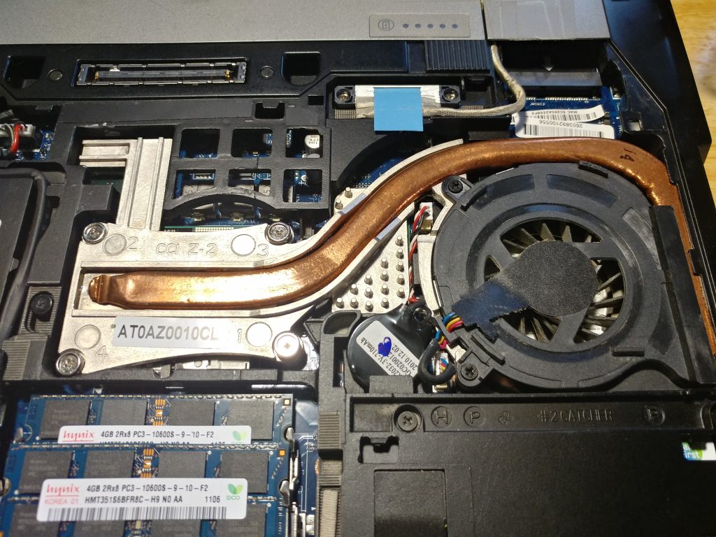
I had a use for it this afternoon, and an hour to spare to look it back over, so I went ahead and pulled the heat sink back off to get a look. It’s easy to get to on these – one screw and the bottom cover slides off, two screws to remove the fan, and four to pull the rest of the heat sink. It’s one combined unit for the CPU and GPU:

laptop heat sink
Dell Latitude E6410 heat sink

I still had decent thermal paste that hadn’t hardened, and the radiator on the right hand end wasn’t clogged up. I could hear the fan working. But I finally spotted the problem – the GPU wasn’t making very good contact with this oddly shaped heat sink module! The CPU would purr along at 47C, and the GPU would shoot up to 95C and trigger a shutoff within minutes.

Since this machine was already “technically trash” and had one foot in the recycle bin, I said heck with it. The GPU is under the little, studded bit of the aluminum casting, right under where the copper heat bar reverses curvature. I pulled the assembly back out, took it in both hands, and just bent the heat sink bar. I bent it down in the middle as shown, so that with the radiator in its case slot on the right, and the CPU screws mounted, it might have a shot in heck of actually having the heat sink properly contact the GPU.

Turns out that’s all it needed. Now it’s sitting here with the GPU running at 47C as well, and it’s useful again. Not bad for a machine I was about two minutes away from drop kicking toward the recycle bin.

So, if you’ve been wading through the dozens of search results on overheating E6410s, and you’re at your wits end – pull the heat sink off and bend it to get better contact. It’s quick, easy, and you might well save your sanity, too.

Update 2021-03-17: This little machine has now been running for eight days straight, without a single GPU excursion over about 60C that I’ve noticed. This was just bad contact between the GPU and heat sink all along. Heck of a note … but it bodes well for getting a few more years use out of the thing!

ROOter GoldenOrb Hosting

We’re helping provide overflow hosting space for the wonderful team that keeps this OpenWRT fork going! However, during this morning’s transition, I hear a few people are having cache problems that have redirected them here to the blog front page, instead of the upload and build folders.

If that’s you, here are your direct links to the new folder locations:

http://www.aturnofthenut.com/upload/

http://www.aturnofthenut.com/builds/

Hopefully the redirect issues will clear up quickly. However, if you ever land on my front page accidentally, there will also always be a link at the top of the page with direct links.

Thanks for your patience!

Remote Logging from OpenWRT to Rsyslog

This one is brief and simple. I have six routers going right now (and a ridiculously long article still in draft explaining why), all running OpenWRT. I had them set to save logs to local thumb drives, which, frankly, was a pain in the butt. I concluded that I wanted them all logging to a single remote system for simplicity – the old EEE PC netbook that I use as a network terminal for basic maintenance. It has a good old fashioned spinning disk hard drive, and won’t suffer from a ton of log writes like the thumb drives (or heavens forbid the internal storage) on the routers would.

After going through several tutorials that were either a bit complicated or a bit incomplete for my specific use, it turned out to be obnoxiously simple to implement. I could’ve gotten it all done in under half an hour if I’d already known exactly what I was doing, and most of that time was repetitively ssh-ing into six different routers.

That said, here it is: quick, dirty, with no missing or extra steps!

Set up your log server first

My logserver is running Debian Buster, which already came with rsyslog configured with very sensible basic settings (logging to file in /var/log/, and rotation already set up). All I had to do was enable listening on TCP or UDP 514 (I’ve opened both but am using TCP), then set up some very basic filtering to sort the remote messages the way I wanted.

All changes can be accomplished quickly in /etc/rsyslog.conf. Starting at the top, we uncomment the lines that start the server listening:

# provides UDP syslog reception
module(load="imudp")
input(type="imudp" port="514")

# provides TCP syslog reception
module(load="imtcp")
input(type="imtcp" port="514")

# List of sub networks authorized to connect :
$AllowedSender UDP, 127.0.0.1, 192.168.0.0/16
$AllowedSender TCP, 127.0.0.1, 192.168.0.0/16

The last group there was added based on the recommendations of a tutorial, and restricts senders to localhost and my local network (I have hosts on five subnets, most people could be using 192.168.1.0/24 or whichever single subnet they’ve configured).

Next, near the bottom of the file, you need to decide how you want your messages stored. If you don’t change anything, they’ll be mixed into your other logs from your localhost. You can do a lot of more complicated things, but I wanted one subdirectory per remote host, with all messages in a single syslog.log. Here’s how you get that, in the rules section and above your rules for normal localhost messages:

###############
#### RULES ####
###############

#
# ADDED BY CHUCK
# Redirect all messages received from the network to subfolders first
# From example on stackexchange saved in notes.
#

$template uzzellnet,"/var/log/%HOSTNAME%/syslog.log"

if $fromhost-ip startswith "192.168." then -?uzzellnet
& stop

The template can be named anything. This test checks all log messages to see if they are from remote hosts in my local net – if so, it sends them all to a single file based on the remote hostname. The template statement must be before the test, and “& stop” tells it that any logs meeting this test should not be further processed below with localhost messages.

Obviously your log server will need a static IP to do this job. If you haven’t set one already, you can either set it manually from the server, or (my recommendation) just configure your DHCP router to automatically provision that machine with a static IP.

That’s it for configuring the server! It really is that simple. Just restart rsyslog on your server:

chuck@raul:/etc$ sudo systemctl restart rsyslog

Now, set up each remote OpenWRT host

All settings for logging are stored in /etc/config/system. By default, everything is logged to a ring buffer in memory, and lost on reboot. Not useful if something happens that causes a lockup, etc., but it is awfully handy to read from the command line when you’re already logged in via ssh, so we want to keep that functionality – messages should both be stored in the ring buffer and sent to the remote server.

In /etc/config/system, add or change the following three lines (using the static IP address you’ve provisioned for your log server):

        option log_ip '192.168.1.209'
        option log_port '514'
        option log_proto 'tcp'

You can leave it the default UDP if you prefer – there’s less network overhead, but most of us aren’t really hurting for network capacity. TCP is generally worth it for logging unless you really don’t care if you miss the occasional message.

Now, just restart your logs so the new settings are picked up:

/etc/init.d/log restart
/etc/init.d/system restart

Next, log a test message. It can say anything. This was the one from the last of my six routers to configure, a test machine I’m still setting up to replace one of my production routers soon:

root@FASTer2:~# logger "First test message from Faster2!"

That should produce a log line both locally and remotely. Check the ring buffer:

root@FASTer2:~# logread
Thu Dec 17 20:22:07 2020 daemon.info logread[424]: Logread connected to 192.168.1.209:514
Thu Dec 17 20:22:21 2020 user.notice root: First test message from Faster2!

Now, on your log server, you should see a new directory for your host created in your log folder (probably /var/log/ if you’re using Debian defaults). We said in rsyslog.conf earlier that the file should be in that subfolder and named syslog.log, so let’s test receipt:

chuck@raul:~$ sudo cat /var/log/FASTer2/syslog.log
[sudo] password for chuck:
Dec 17 20:22:07 FASTer2 logread[424]: Logread connected to 192.168.1.209:514
Dec 17 20:22:21 FASTer2 root: First test message from Faster2!

That’s it! We’re all set to go. You can obviously get way more elaborate than this, but a simple 1:1 replacement of OpenWRT’s default ring buffer with a neatly sorted single log file will probably cover most users’ needs.

Enjoy!

C&O in Norfolk, VA – Brooke Avenue Yard

One interest of mine that hasn’t yet appeared on this sporadically updated blog is trains.  I grew up in a railroad town, with mostly railroad friends, and largely in a model train store (which also eventually became my first job at 15).  It’s a hobby I’ve had neither time nor space to pursue in 20 years, but the interest is still there, and of late the bug has been biting again.

My rail line of choice has always been the Chesapeake and Ohio, and I grew up along the James River subdivision.  However, some time meandering through Carl Arendt’s Small Layout Scrapbook led me down the rabbit hole to Brooklyn’s offline terminals.  That piqued my curiosity, and some Google meandering lead me to Bernard Kempinski’s excellent blog post on C&O’s Brooke Ave. yard and Southgate Terminal, which I understand was also featured in an article he wrote for Model Railroad Planning 2002.  To the best of my knowledge, this is the only offline terminal on C&O’s original pre-merger network.

I’ve walked the present site of Brooke Avenue yard many times myself over the years without even realizing what had been there; it’s well within my usual walking range on the (increasingly rare) occasions when things are quiet enough to take a long lunch at work.  Needless to say, it grabbed my imagination, and I’ve spent the last two weeks digging up a lot of information on this facility.  Very little solid information is available online, and it turns out I already have access to more offline information than most people for this site, between being walking distance to Norfolk Public Library’s Sargeant Memorial Collection of local records, and having access to a handful of old engineering records from my own engineering firm’s old surveys of the area.

Brooke/Southgate overview.
Overview of Chesapeake and Ohio Brooke Avenue Yard and Southgate Terminal, 1948.

As I can, I’ll begin compiling that information here in a series of subsequent articles, linked below as I complete them.

Brooke Avenue articles:

  • Site History
  • C&O Structures and Business on Site
  • Southgate Terminal
  • Connected and Tenant Industries
  • Locomotives
  • Modeling
  • Modern Disposition

Alternators with multiple battery banks

I got into an excellent discussion elsewhere on how alternators work with multiple battery banks and isolators.  It’s not completely complicated, but it takes a lot of words to try and explain and make sense.  After scouring the internet for good illustrations and finding none, I ended up whipping up my own, and wanted to clean up my response afterward, expand on it, and make it a little easier to read.

The very silly TL;DR summary with multiple battery banks at different states of charge is that your auto electrical system is very socialist.  “From each (alternator) according to his ability, to each (battery) according to his needs.”  This is true with small tweaks whether your isolator is a relay or a diode, too.

What exactly happens when one alternator charges two batteries?

In a situation where you have an auxiliary battery connected to your starting battery with an isolator in between, how does the alternator’s regulator react? Lets assume the starting battery is at full charge (12.7v) and the aux battery is at half charge(12.0v)

From my understanding, the regulator would see a voltage of something in between the two, say 12.3v and continue to put a high voltage instead of trickle charging it to prevent damage.

Is my understanding completely off?

Lets say the starting battery is 95% and the house battery is 50%. In order for the current to get to the house battery, it would have to pass through the starting battery. And since the starting battery is still a lower capacity than the alternator gives, how does it not take in anything?

This question actually came up because I left the car heater vent on the lowest setting for days and didn’t realize it. Usually the dashboard shows the charging needle slightly tipped towards ‘Charge’ when I’m driving. This time, with the starting battery half drained, it was outputting much more current. What I noticed was, it also charged my house battery much faster too.

After a little discussion, I got a bit more good information from the original poster.  He has an 88 Econoline with a factory battery isolation relay and alternator, so I was able to cook up illustrations that were at least reasonably specific to a particular vehicle.

I had originally wanted to grab a couple of illustrations to make it make a little more sense, but after scouring the internet to see if anyone already had the right illustrations up, no one did. No wonder nobody usually understands how this stuff works. You can find illustrations all day of battery voltage during charge or discharge, but I never did find a chart of voltage (at a specific level of charge) as it changes depending on how much current you’re putting in or pulling out right at that moment, which is what you need to understand this.

I did enough hunting to make sure my information is right, and just did up my own illustrations after work one evening.

How does each piece of the system work on its own?

Before any of this makes sense, you need to be able to see how each piece acts under different electrical loads, but there are a lot of variables that change things. These illustrations aren’t *accurate* per say to any particular setup, but they’re “about right” for the stock 2G alternator and starting battery you get in an E-150 from around 1987-1994 or so, and hopefully just good enough to explain the concept.

Alternator

Most of the graphs for those show the max output current you can get depending on the alternator or engine speed, which doesn’t really help us much. What you really need to see is what your alternator will do at a fixed cruising speed as you increase the load on it.

Estimated and eyeballed; one day I'd like to set up a test bench to get real data for this instead.
Estimated and eyeballed; one day I’d like to set up a test bench to get real data for this instead.

At cruising speed, you can see the voltage output of your alternator is mostly flat up to somewhere around its rated output, and somewhere after that, as you put more load on it, the voltage it’s able to put out drops. For the flat part of the graph, the voltage regulator is cranking the field up in the alternator to keep the voltage up. Once the field is at full strength, that’s all you have, and the voltage drops quickly after that as you increase the demand for current.

This does change as your engine speed changes.  At idle, with the anternator only turning about 2,000 RPM (usually about 3x crank speed), the cutoff point moves a lot farther to the left.  At cruise, most Fords will have the alternator turning anywhere from 4,000-6,000 RPM, and this is probably pretty representative of that.  If you’re running the engine faster, it does push the cutoff further to the right, but not by as much; you get to a point where all the resistance in the components basically wins out over spinning the alternator faster.  Most Ford alternators are good for around 16,000-18,000 RPM before things start breaking.

This curve isn’t accurate or based on real test data, because unfortunately I don’t have any and couldn’t find any.  This one’s based on information for separately excited alternators available in engineering texts, and modified with adding in the behavior appropriate for having a voltage regulator.  So yes, I’m sure this is what the curve looks like, but at the same time, no, I’m not confident of a single exact number on this graph, since I’ve adjusted it by eyeball.  Anyone want to get together and make an alternator test bench so we could get real numbers?

Starting Battery

Next up is what your starting battery does at different current levels.

Start battery at 90

This was the hard part to find, and I ended up extracting this info from some really good battery charts put together by a boat guy for Home Power magazine.  These battery graphs are actually at least based on someone’s experimental data, so they’re a little more accurate than the alternator graph I have above.  To get this graph, I essentially took the chart on the last page of the linked document, and took the values at one “slice” at a specific state of charge (90% for this first curve), then adjusted for the battery size.

Everything on that curve above changes with both how big your battery is, and how discharged it is, so I’ve made one for each of the different situations we’d need to look at to understand how isolators and multiple battery banks work together. For this first one, it’s assuming about a 75Ah lead acid battery (basically the Group 65 battery in an Econoline).

As you look to the left of zero on the bottom, that’s discharge current, with your battery supplying power. To the right is charge current, with power being put into your battery. What you can read roughly off this chart is the voltage. This chart has about the right voltage numbers for your starting battery being 90% charged, which is pretty normal for just having fired up a van that’s sat for a little while.

The least accurate part of these charts is right around 0 current.  Lead acid battery behavior is very “fuzzy” in this area, and the voltage depends on a lot of other things, so don’t pay much attention to the line that connects the lowest “charging” and “discharging” currents; it doesn’t mean a lot there.

The simplest system: One alternator, one starting battery

Low Load

Now, let’s look at the first and simplest combination, just your alternator and your starting battery. Right after you fire up your van, the alternator kicks right up to 14-14.5V or so. Your van’s fuel pump and electronics are taking maybe 30A to run, so your system will probably be at around 14.2V – you have to “guess” first to figure this out, and then go back and add things up to see if your guess was about right.

What’s important to see is that your battery and alternator are tied together, so they *have* to be at the same voltage. At 14.2V, your alternator can put out about 42A, and your battery “wants” about 7A worth of charge, so 14.2V would be right if the rest of your system is demanding about 35A right then.  Pretty close, but maybe not quite a good a guess as we can do, because the currents don’t quite balance out – your car and battery want 37A together, and the alternator wants to put out 42A, so we’re off a little.

I can skip a step and say 14.3V works out too high, so let’s try halfway between at 14.25V.  At that voltage, the start battery wants 7.5A, and the van still wants 30A to run, and the alternator wants to put out 35A.  That’s pretty darned close – within a couple of amps – so I’d call 14.25 the answer.  It’s probably a little bit too precise considering how rigged up the charts are.

Medium Load

Now with that simple one alternator/one battery combo, let’s crank on the headlights and turn the fan on low; now we’ll say we’ve raised our load from the van to 50A.  Let’s guess 14.1V for the system voltage.  Looking at the battery chart, the battery charge current is probably going to drop to more like 6.5A at that voltage, so your total load is now about 56.5A.  Your alternator graph says it’s putting out about 56A at that voltage, so our guess was good!  56A coming out of the alternator will split into about 50A going to the van and 6A going to the battery.

High Load

Okay, time to overload the alternator. Crank the heat on max (those blowers draw about 20A on max), turn on the rear air, and maybe heated seats. Flip on the wipers, get everything going. Now we’ve got about 90A of demand in the system. That’s way more than the alternator can put out by itself at above 12V, so if you trust the slightly fictional chart I made, your alternator can only put out about 11.5V at that load.

Battery to the rescue! It’s still connected, and if it were actually at 11.5V, it would really be putting out some juice! What’s really going to happen is that the system is going to settle at whatever voltage the output current from the battery and the alternator add up to 90A.

Looking at the chart, that looks like about 12.4V to me. At 12.4V, your alternator can still crank out 83A, and your battery is going to put out the remaining 7A.

The Simple System TL;DR

I picked the simple situation first because this one has to make sense before you can understand what happens when you throw in a second battery bank with a different charge. In this simple example you already have two things that can put out power (alternator and battery) that have to “decide” how to share the load. The thing is, it’s not really so much a “decision.” Each thing has it’s own natural behavior that the chart tries to make sense of, and the system has one “natural law”, which is that the voltage for all the pieces we’re looking at will always be the same (because they’re directly connected). Hence, the alternator and battery will increase or decrease output until the voltage stabilizes between them. It’s a bit of a physics balancing act.

Adding an AUX/House Battery Bank

Low vehicle load, 50% Aux battery charge

Now, let’s go back to the first example where you’ve just started the van and have a reasonable 30A system load, but now we add in your house batteries. Let’s say your battery bank is 200Ah, equivalent to almost three of those starting batteries in size – I want to exaggerate things a little so it’s easier to see the effect in the different charts. Your battery bank is only 50% charged when your isolator relay connects it to the alternator and starting battery, so its chart looks like this.

House battery at 50

The shape is really similar, but the currents are much bigger (because the bank is bigger) and the voltages are lower (because the bank is half discharged). Your van’s system still wants about 30A to run its own stuff.

So now, with that isolator relay connected, the “all the voltages are the same” law applies to all three pieces. To figure out what it’s going to do, I have to guess a voltage again to start. I can make an educated guess and say maybe the system will run at 13.5V, which looks pretty close. Let’s see, at 13.5V our alternator puts out about 76A, and our demand is 30A (from the car’s electronics) plus about 3A (what the mostly charged small battery wants at that voltage) and a whopping 65A that our hungry battery bank wants at that voltage. That’s a total load of 98A, way more than the alternator is putting out, so I’ve obviously guessed wrong!

If I try again it comes out closer – At 13.4V, the load is 30A car, still about 3A starting battery (too small a change to tell from the chart), but down to about 40A on the battery bank. The alternator can put out just a few more amps, too. So the load goes down to 73A, and the alternator’s capacity creeps up to maybe 77. Basically, we’re about there; 13.4V is about as accurate as we can get with these charts.

With that example, you can really see how the power gets split between the two battery banks. Your starting battery doesn’t want much; it’s too full to take much more charge at that low of a voltage, and the voltage is still too high for it to discharge at all. Meanwhile, your aux battery bank is hungry, and it’s just going to suck current in until it drops the alternator’s voltage down to a level where it’s being satisfied.  As the current goes up, the alternator’s voltage drops, and as the voltage drops, the aux battery’s “hunger” drops, so they meet in the middle.

Low vehicle load, 50% Aux battery charge

Now, to see what was going on with your rig the other day when your aux bank was really down, here’s a curve for your aux battery at only 20% charge.

House battery at 20

This is enough of a difference to start to suck juice out of your starting battery, just like you saw, though not much at all yet.

I’m going to guess 12.7V first. At 12.7V, your alternator is putting out about 82A, your start battery is actually putting out about 1A. Your van still wants 30A to run, and your aux battery wants to suck up a full 50A! That’s probably a pretty good guess on the voltage, we’re within a couple of amps of everything adding up. 83A or so from the alternator and start battery, and 50 of it going into recharging the auxiliary bank.

You can see where even small changes in my guesses on making those graphs would make it draw harder from your starting battery.

  • If your aux was less than 20% charge left, you’d definitely pull a lot harder from the starting battery, since your alternator is completely maxed out.
  • My “alternator curve” could easily have been generous for that alternator over 70A, too, since I just cooked up that part of the curve “by eye” until it looked right. Unlike the batteries, I don’t have good hard data for that one, just enough basic knowledge of how it works to cook up a chart.
  • The smallest increase in load from the van itself is going to come almost straight out of your starting battery now, with house battery charge current decreasing.  The alternator is almost completely maxed out,  so if you turn out the heaters for 10A (for 40A total for the van), the voltage drops a tiny bit to 12.68V, your alternator still produces about 82A, the starting battery puts out about 2A, and your aux charge current drops to only 44A (for an 84A total load).  Doesn’t sound like much, but the ammeters in the Ford dashes are actually really sensitive, and you’d definitely see that as a very noticeable needle twitch.

On the other hand, this goes to show why you shouldn’t worry too much about a relay isolator causing your aux batteries to “drain” your start battery when the car is running.  You have to really drain down your house batteries before they even start pulling any current out of your start batteries, and even then, it’s a tiny trickle.

At the same time, you can see how recharging the house batteries from a really low charge really works the snot out of the alternator.  Not a good part to cheap out on.

What about a diode isolator?

A diode isolator does change things, and not always in a good way.  It does guarantee that your house bank won’t pull charge directly from your starting bank when you’re running.  However, as you can see from the examples above, that’s not really a big risk even with a simple relay.

What a diode isolator definitely does is change the shape of the alternator curve.  Diodes have what is called a “forward voltage drop” when they’re working.  This is basically a fixed voltage loss whenever current is flowing.  I understand for most alternator diodes this is about 0.9V.

To compensate for this, the “voltage sensing” wire for your voltage regulator is still attached at the starting battery, on the downstream side of the diode (do not attach on the aux battery side instead).  If your regulator wants 14.2V, it’s going to crank the field on the alternator higher, until the alternator is putting out 15.1V.  This will produce 14.2V on the downstream side of that diode.

This affects alternator performance three ways:

  • It adds load to the alternator.  If you’re producing 50A, you are losing 45W crossing the diode, so that’s another 45W the alternator has to put out.  This means your alternator will always run a little hotter.
  • It reduces the alternator output where the regulator maxes out.  Because it’s taking extra field strength to supply the extra 0.9V, your regulator will run out of the ability to add extra “kick” at a lower output current, so you “fall off” the flat part of the curve earlier.
  • You lose voltage everywhere above that flat spot for a given current, so your charge performance when the alternator is maxed out decreases very measurably.

I’ve made another rigged up chart that shows this behavior.  The overall curve isn’t the most accurate, but the difference in performance is pretty on-the-mark.


Ouch!
Ouch!

The original alternator curve is dotted.  I’ve stretched the graph a little taller to make the differences easier to see.  It’s a little squiggly from 14 to 13V, but overall it’s about right.

As you can see, there’s not much difference when you’ve got a low load.  However, once you’ve maxed out your field, whoa!  What a difference.  The alternator that was rated at 67A would probably be rated at about 58A now if you used the same criteria.  You lose almost 5A all the way through the range.  All your lost power is going into the 50W+ or so that your diode is eating.

This is why I like isolator relays.  Even at the very high currents you get recharging a 200Ah bank that’s drained way down, I can get a continuous duty solenoid that will handle the current for $40 tops.  I’d much rather spend the extra money you’d pay for a diode isolator (about $35 extra minimum for this alternator size) toward a much better alternator instead.

So what’s really going on here?

Nothing in the system really knows how to distribute the electricity, each piece just has it’s own performance characteristics, and the system will “balance out” naturally to whatever voltage makes the available supply (from the alternator) meet the demand (from the car electronics, and the two battery banks).

Plus, diode isolators are the devil!  (Your mileage may vary)

An update on last year’s distributor failures

I thought I’d add in an update on the (hopefully) final resolution of last year’s 300 I6 distributor trouble.  I had one more failure, not long after my last post, and it was a particularly inconvenient one.

On 6/13, the roll pin for the distributor gear fatigued.  Thankfully, it didn’t completely shear, but it did lose a layer on both ends, which means I lost about 20* of timing and all power.  Unfortunately, it did this at 70mph, on a 95*F day, in the left lane, passing a semi on the interstate while pulling a loaded stock trailer, with a truckload of our good working dogs, 130 miles from home.  I can think of less pleasant breakdowns, but not too many.  This represents about 2,000 miles at most on this particular distributor install.

Thankfully, we were only twenty miles from a friend’s farm, and she came to our rescue.  We left our rig and stock at her place overnight, and came back the next day with a couple of spare roll pins and enough tools to replace one roadside.  We carefully limped everything home, and I started doing a postmortem.

My final conclusions on the problem came down to:

  • Never re-use a roll pin in a distributor.  The pin that sheared was the original pin from the Rich Porter.  It may have been low quality to start with.  Use an upgraded new pin every time you pull one out.
  • You can’t get a properly made 300 I6 distributor, remanufactured or aftermarket.  You’re going to need to do some careful re-engineering to reliably use any replacement you get.
  • For the love of all that is holy, if you have a factory distributor that isn’t absolutely FUBAR, don’t replace it!  I’ve never, ever personally had a distributor failure on a Ford that still had it’s factory distributor and where no one has screwed with it.  Maintain or repair as needed, but any replacement you get is likely to be worse than the broken unit you’re pulling.  I have no idea why the original part was swapped out on this engine before I bought it, but I’d wager good money it was because someone was throwing money and parts at a problem that had nothing to do with the distributor.

Here’s why your new or reman distributor is most likely to experience roll pin fatigue failures.  The distributor gear should be a press fit on the shaft.  That press fit should be what’s carrying all the load, and the pin should basically be a safety device.

However, the machining on new distributors is crap, and you can almost bet any reman you get will have had a failure which spun the gear on the shaft (my reman NAPA Echlin arrived that way).  Either way, every distributor I’ve put in during this saga has had a distributor gear I could turn on the shaft by hand without the pin installed.  The combo that fatigued on me was the loosest, and when you combine it with re-using the cheap pin that came from the RichPorter, you can see why it died.  In fact, when I re-pinned the NAPA and drove it carefully home, the pin I popped in (which was the original NAPA pin) had already started to fail when I pulled it out that evening – under 150 miles.

My solution to this has so far worked for six months and about 10,000 miles.  First, I bought a 100 pack of brand new, high strength roll pins.  They are about 30% stronger than the standard roll pins of this size, and probably almost double the strength of the off brand pins that came with both the Rich Porter and the NAPA reman.

Second, I went ahead and bought a brand new Rich Porter, with the intention of immediately tearing it down.  They are almost the only game in town in terms of new 300 I6 distributors, and if I’m going to start with junk either way, I’d rather it be new junk with a lifetime warranty.  Upon arrival, I immediately pressed out the crappy stock pin, pulled the gear (which was loose, but a lot better than the NAPA unit started out), and removed enough end play shims to get the end play up to 0.030 where I wanted it.  I really didn’t want a repeat performance of the original Rich Porter getting too tight and popping it’s hall plate off the top splines, since that was the only problem I actually had with the original Rich Porter.

After a careful break-in and timing set, that combo has now been in for about 10,000 miles, including plenty more miles on the interstate with the stock trailer.  That means this has also lasted at least 6,000 miles more than any other distributor we’ve had in it since purchase last year.

I was also determined not to get stuck by a failure again if I could help it.  I replaced the already fatiguing “new” pin in the NAPA with a new high strength one, and have that crap distributor and enough tools and spare pins to change and repair it roadside sitting in the van’s toolbox.  I’ve got that routine down to about 20 minutes, which is a lot faster than the tow truck showed up.  I just checked the pin by feel last Friday (the shaft movement feels “soft” when they’re starting to break), and so far it still feels good, with no measurable timing loss with the light either.

I’ve seriously considered selling these nice little pins as singles or small packs on eBay or Amazon.  At $2 a pin plus the cost of a stamp and an envelope, they’re a lot cheaper than the 100 pack I had to buy, and cheaper than the single pins anyone else is selling online (mostly $5 and up).  You can’t get them in quantities less than 100, and I hope to never use up the other 99.  They’re high strength steel and have a minimum double shear break strength of 2,000lb, which means they are good for 44 ft-lb for the distributor gear in a 300 or 351W, or 39 ft-lb in a 302 (smaller shaft).  I’ve got the info on them if anyone wants them, or would probably mail a few for a couple of bucks plus postage.

Here’s hoping this helps someone else out, too.  I’ll update again if I ever get another failure with this.  Meanwhile, I’ve seriously started considering getting my own shafts machined so I can actually get a proper fitment.  Most likely I’ll probably end up swapping in the spare 302 I have instead, though.  The 300 isn’t the best in the world right now with a stock trailer at 70.

How are engine displacement and power/torque related?

I got involved in a discussion elsewhere on this topic, and wanted to share my response here as well.  This is meant to be a solid explanation in layman’s terms, for those who don’t want to dive down a big physics and thermodynamics rabbit hole!

While I’m an automotive engineer I’m ashamed to say that I still don’t really understand the relationship between displacement and power/torque produced. While I assume that the difference between the 1000+hp – 8l engine in the Veyron and the 645hp – 8.4l engine in the Viper is mostly determined by turbos I would prefer a more detailed explanation.

Leaving out for a moment questions of efficiency, turbocharging, and a lot of other smaller factors:

  • Torque is most proportional to displacement. This is mostly a matter of how much fuel you can burn per cycle of the engine. Torque is a force, and applies to questions like, “how heavy a car can I push up this slope?”
  • Horsepower is proportional to the product of torque and engine rpm. There’s a constant in the equation, but otherwise it’s a direct relationship. Power applies to the question, “How fast can I push this 4000lb car up this slope?”

Everything else is just a factor that modifies those two variables. Let’s take the steady-state example of a truck climbing a steady grade at a steady speed – it’s actually simpler to understand than everyone’s favorite “drag race” example. Want to increase the amount of load you can carry up the hill at a given speed (increase the power)? Here are the ways you can do it:

  • Make the engine bigger. If everything is proportional so that your efficiency is the same, your torque will go up proportionally as well, because you’re ingesting more oxygen and burning more fuel. This means your power will also increase proportionally. More torque at the same speed (more power) means you can pull a heavier load up the hill.
  • Spin the engine faster for the same road speed (RPM). You’re still making roughly the same torque at the engine, but to maintain the same road speed, you will have had to change the axle/transmission gearing. This gives your same engine torque more “leverage” on the road. This example both shows the difference between torque and power, and shows you why it’s power that matters for climbing hills. Looking directly at the power really tells you what your engine can do at a given road speed once you’ve factored in all the gearing – it simplifies everything (better tool for analyzing that type of job).
  • “Fake” making the engine bigger. You can do this with turbocharging, supercharging, nitrous oxide … your choice. Either way, you’re using an external component to force additional oxygen and fuel into your engine, faking the behavior of larger displacement. The result is more power. This solution will almost always be more efficient for some operating conditions and less efficient for others, so you get to pick where you gain and lose economy, too. You have to do more work “stuffing” in the extra air, which reduces efficiency, but it can let you tune for better efficiency when you don’t need full power. Ford Ecoboost is a good example of this idea.
  • Improve overall efficiency. You can do this by increasing compression, tweaking your spark timing, mechanical/frictional tweaks, anything that gets more of the energy from your fuel to your tires instead of going out the tailpipe and radiator. You tend to be pretty limited by your fuel quality here compared to the first three options.
  • Improve efficiency at the engine speed you’re operating. Change your valve timing. Here, you’ll trade better efficiency at the RPM you care about for worse efficiency elsewhere. Your limit here is that you still have a “peak” torque value proportional to displacement, which you can move around with valve timing but not really increase. Assuming you don’t change your gearing (RPM) at the same time, once you get to the point where your peak torque is at the RPM you’re climbing the hill, you’ve gained all you can with this option.

In short, power is everything. Torque only really matters in that you’d like most of it to be “well distributed” across engine RPM, instead of very concentrated in a narrow band – this just makes your engine more versatile and nicer to drive. However, for pulling a hill, etc, the question of “not enough torque” is always solved by “more gear”, because the power is the same either way; that power is really just a matter of how much oxygen you can stuff in, and how much heat you lose from there to the tires.

For a good comparative example, consider the difference between the 110ci engine in a Miata and the 300ci engine in a mid-90’s Ford. I have both. Both make roughly the same HP, plus or minus a few – around 140.

The Miata has high compression, good mechanical efficiency, and all of its variables (valve timing, etc) are tuned to maximize the available torque and power from 5,000 to 7,000 RPM. It’s torque curve is very peaky, maxes out at about 115 lb-ft, and below 3,000 it’s essentially worthless. This is okay for acceleration, because everything is lightweight, and the car has very steep axle gearing (4.56:1) to try to keep it where it makes some power. However, you’d never want to tow anything with this engine, because the high RPM and compression really limit reliability if you needed to make the full 140 horsepower long enough to, say, climb a 10 mile hill, something you’d never need in a 2500lb car even at full speed. You need five (efficient, manual) gears at a minimum to keep this little engine where it will get out of its own way, and you’re shifting constantly in hilly terrain and traffic.

In contrast, the 300 is in a 90’s van with a three speed automatic, probably the most reliable but inefficient transmission Ford ever produced. Because of the massive energy-suck of the transmission, considerably less of this engine’s power gets to the road than the Miata’s. It’s in a vehicle that weighs double what the Miata does, and which will happily tow its own weight – so this engine is happy moving four times the load of the Miata. Why? Rather than focusing on a narrow “happy” spot, the design focused on distributing it’s torque out well. It doesn’t have overwhelming “go” anywhere, with only 260 ft-lb of peak torque limited largely by very low compression compared to the Miata; at the same time, what “go” it has is available everywhere (over 200 for almost the entire operating range). It makes its maximum power at only 3500 RPM, which it will happily do all day long, on crappy fuel, in lousy, hot, humid weather. Because the torque curve is so flat, you almost never find yourself shifting for any hill but the most extreme. It’ll never get anywhere as fast as the Miata, but it will go everywhere with extreme reliability doing four times the actual work, strolling along like a big, dopey draft horse.

You can dive down the rabbit hole all day with the hundreds of smaller variables that affect torque and power, but sometimes the basics are better summed up with no math and a little example or two. If nothing else, hopefully this version was entertaining.